USD
 INR

Call Us Now
+91 9106756572
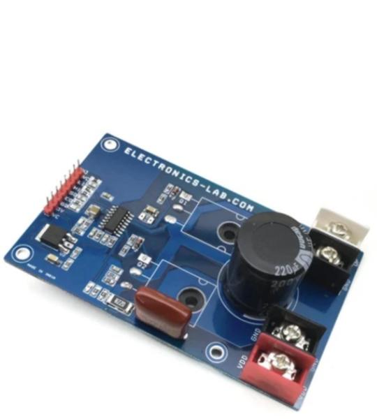
The project presented here is a versatile high voltage Half-Bridge with current feedback. The board is built using L6390 IC from ST Semiconductor. It is suitable for DC-DC converters, EHT drivers, induction heater drivers, battery chargers, LED drivers, DC motor speed controller and field-oriented control (FOC) motor driving application etc. The user can make a FOC Brushless motor driver with 3 of these units, Bidirectional Brushed DC motor can be controlled with 2 units. FDH3632 MOSFETs rated at 100V DC and 80A Current drive the output. Other High voltage and high current MOSFET can be used as per voltage and current requirements.
The project presented here is an Ignition coil driver featuring FAN1100-F085 ignition gate driver chip and IGBT. Chip is designed to directly drive an ignition IGBT and control the current and spark event of the coil. The coil current is controlled via the input signal pin. When the input is driven high, the output of the chip is enabled to turn on the IGBT and start charging the coil. Output sink current is programable using resistor R5 (RA). An input spike filter suppresses input signals of less than 13uS in duration. A Max Dwell timer is included in the chip which will turn off the IGBT if input stays active for longer than the programmable time. This time interval can be modified through an external capacitor on the CSSD pin. When the Max Dwell timer is exceeded, the CHIP will enter a Soft-Shut-Down mode (SSD) slowly dropping the collector current by lowering the gate drive to the IGBT thereby discharging the coil such as to inhibit a spark event. Once the soft shutdown operation has started, any transition on the input signal is ignored until after the completion of the soft shutdown function. Chip also limits the collector current of the IGBT during charging. This is done through the sense resistor R6 in the emitter leg of the ignition IGBT developing a signal input to the V-Sense pin of the chip.
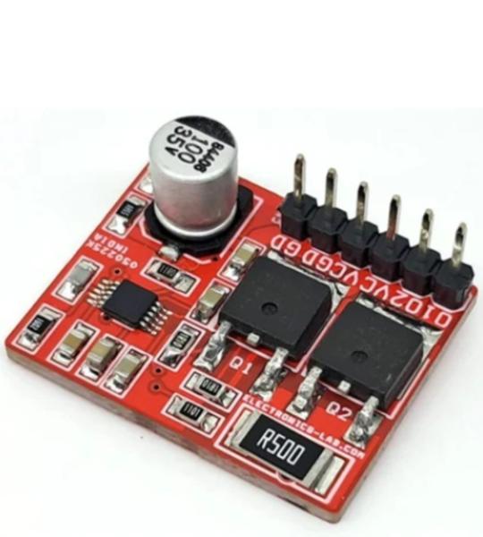
This is a simple low voltage push-pull voltage mode PWM controller based on LM5032 chip from TI. The board is build around LM5032 chip and two 100V 7A MOSFETs. It can be used in simple DC-DC converter, Tesla Coil Driver etc. The frequency can be changed with resistor R5. Resistor R7 play roll of current sense. Capacitor C4 configures the soft start function. Output is square wave open drain.
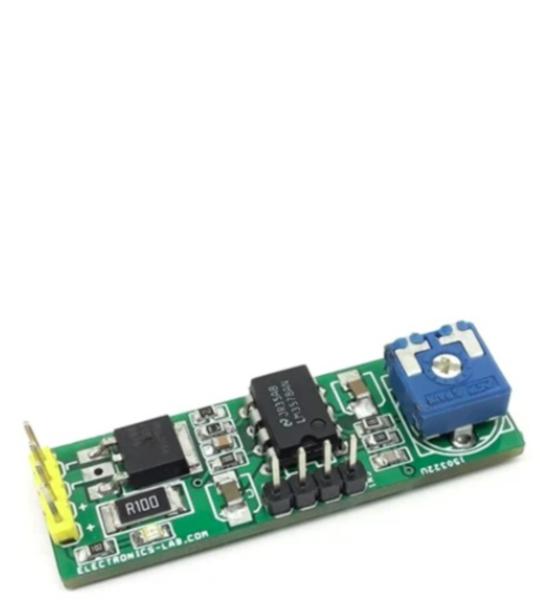
This Low-cost LED dimer project includes two main parts, an LM3578 chip, and a MOSFET. The LM3578 generates a PWM signal, and Q1 MOSFET helps to drive a high current LED. The project also includes current limit feature. Over current trigger point is set to 1.1A. LED intensity can be set using a board trimmer potentiometer. The compact and low-profile circuit occupies a very small area. PCB has the option to mount DIP8 IC or SOIC8 IC.
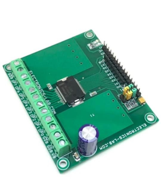
This project provides 8 fully protected and isolated high-side power switches that are able to handle current up to 625 mA. An 8-bit parallel microcontroller compatible interface allows connecting the inputs directly to a microcontroller or standalone circuit system. The input interface also supports direct control mode and is designed to operate with 3.3/5V CMOS compatible levels. The signal transfer from input to output side is realized by the integrated Coreless Transformer Technology. The board is designed for industrial applications such as process control and PLC to drive inductive, resistive, and capacitive loads like Relay, solenoid, lamps, heaters, piezo.
The circuit shown here is a low-cost electronic DC load designed to sink current from a power source. This test equipment can be used to test power devices such as power supplies, chargers, solar panels, and batteries. The board is built using op-amp TLE2141, LM385 provides the reference voltage. Resistor R11 acts as a shunt resistor and provides load current feedback to the op-amp, potentiometer P1 is provided to adjust the load current, and D1 is the power LED. A 10-turn Potentiometer is provided for fine current adjustment. The user may use a single-turn PR1 trimmer potentiometer. The load current range is up to 2.5A, and the project can handle higher currents with large-size heat-sink and forced air using a Fan. You may use a 0 to 5A Current Meter in series to measure the load current.
This is a tiny module that allows users to charge small Li-ion batteries, CR2032 or equivalent, from a low power source such as a small photovoltaic cell. The project consists of the LTC3105 step-up DC-DC converter chip which features Maximum Power Point Control (MPPC) and 250mV start-up voltage which enables operational directly from low power, high impedance alternative power sources such as photovoltaic cells. A user-programmable MPPC set point maximizes the energy that can be extracted from any power source. Burst Mode operation, with a proprietary self-adjusting peak current, optimizes converter efficiency and output voltage ripple overall operating conditions. The circuit works with single-cell or dual-cell in parallel. The operating supply of this project is as low as 225mV and a maximum of 5V. Input supply should not exceed 5V DC. The module is programmed to output 4.1V which is important to charge the Li-On battery. Jumper J1 should be open for normal operation, close to disable the output.
This over-current latch load switch provides over-current protection, thermal shutdown protection, soft-start function, and low power OFF function. The Overcurrent protection function is activated when the load is shorted. This protection function is effective in preventing damage due to sudden and unexpected incidents. It is also equipped with an error flag notification pin which indicates thermal shutdown and over-current condition. The project can help to protect the connected device from overcurrent, monitoring of various power lines, and power management. The board operates from 12V DC to 24V DC. The power LED indicates the output. Screw terminals provided for an easy connection of input and output supply. For the Fault function, additional 5V VCC DC input is required, otherwise, the VCC is not required. The circuit is normally enabled, and you can connect enable pin to GND to disable the output. Output is latching type; power is OFF when a fault condition occurs and sequence can be reversed with power OFF or Disable/Enable Pin.
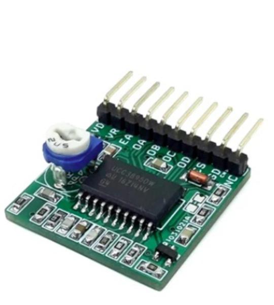
This is a Phase-Shifted Full-Bridge PWM UCC3895 carrier board that contains all of the features necessary to implement a phase-shifted full-bridge topology power converter. All inputs and outputs pins are accessible using a header connector. A highly-efficient DC-DC converter can be created using this carrier board + External H-Bridge and Transformer. Refer to the datasheet of UC3895 and schematic to configure the working frequency, current feedback, delays, etc.
3A TEC Driver Module is a complete power stage solution to drive Thermoelectric Cooler (TEC). The required DC voltage input controls the output current. It consists of the Texas instruments DRV593 power driver IC, along with a few discrete passive components required for operation. It also includes jumpers for configuring the features of the device, LEDs for fault monitoring, and an output filter. The 4 Pin header connector for the inputs, 4-pin header connector for output, and 4 Pin header connector for the power supply provide ease of connection to any system, from an existing design to a bread-boarded prototype. Connect a dc control voltage to CN1 Pin 3 (IN+), ranging from ground to VCC. The Pin 7 of the IC is held to VCC/2 with a resistor voltage divider, as shown in the schematic. Therefore, a dc control voltage of VCC/2 provides 0-V output from PWM to H/C. Input DC voltage range is 1.2V to 3.8V when the supply voltage is 5V and 1.2V to 2.1V when the supply voltage is 3.3V.
The project published here is a solid-state power switch with current limiting that prevents damage to host devices from faulty load conditions. This analog current limit switch has low on-resistance P-channel MOSFET and INA202 driver IC from Texas Instrument. The project operates from input voltage in the range of 5V to 24V and can handle currents up to 2A. The versatile project can be used in Smart Power applications. It is widely used to clamp the overload current and deliver a constant current.
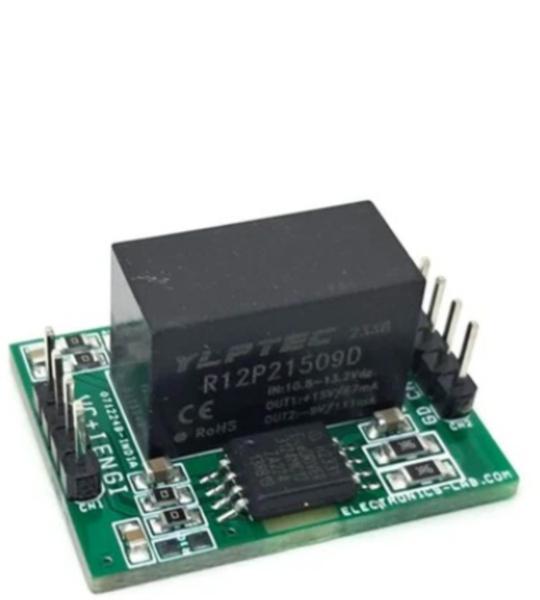
This project design consists of galvanically isolated single channel gate driver IC and dedicated isolated DC-DC gate drive power supply with bipolar output +15V/-9V. This compact module can control IGBTs in inverters. The isolated high current IGBT gate driver module is a simple solution for power drivers, consisting of a gate driver chip 1ED3124MC12H and an isolated 2W DC-DC converter (R12P21509D). This module is optimized for high-frequency operations and can provide high gate driver currents up to 14A, making it suitable for applications such as half-bridge, full-bridge, and single IGBT.
Logic input: for the output switching behavior there are two possible input modes to control the IGBT. At non-inverting mode IN+ controls the driver output while IN- is set to low. At inverting mode IN- controls the driver output while IN+ is set to high. A minimum input pulse width is defined to filter occasional glitches.
Cookie preferences