USD
 INR

Call Us Now
+91 9106756572
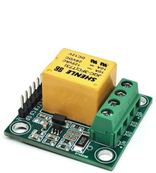
This simple project allows users to design an under-voltage, over-voltage, under-current, and over-current protection switch. It is a highly useful system for safeguarding electrical loads against abnormal power or current conditions.
The project features a relay with optocoupler input, a current-sensing circuit based on the INA195 amplifier, a 10mΩ shunt resistor, and a voltage divider network for voltage feedback. It is primarily designed for low-voltage and low-current applications up to 4A, but the relay can handle loads up to 5 A at supply voltages up to 48 V.
The system can be easily controlled using an Arduino or other microcontroller. Voltage and current feedback signals are fed into the microcontroller’s ADC pins for measurement, while the relay can be switched using a 5 V control signal from the processor.
This simple project allows users to design an under-voltage, over-voltage, under-current, and over-current protection switch. It is a highly useful system for safeguarding electrical loads against abnormal power or current conditions.
The project features a relay with optocoupler input, a current-sensing circuit based on the INA195 amplifier, a 10mΩ shunt resistor, and a voltage divider network for voltage feedback. It is primarily designed for low-voltage and low-current applications up to 4A, but the relay can handle loads up to 5 A at supply voltages up to 48 V.
The system can be easily controlled using an Arduino or other microcontroller. Voltage and current feedback signals are fed into the microcontroller’s ADC pins for measurement, while the relay can be switched using a 5 V control signal from the processor.
Over/Under Current Switch
The INA195 current-sense amplifier measures the voltage across the shunt resistor and provides an output voltage proportional to the load current. This output can be read by the microcontroller’s ADC to implement over-current or under-current protection logic.
The INA195 has a fixed gain of 100 V/V, providing an output of approximately 1 V per ampere of load current. For safety and relay handling limits, the recommended maximum current is below 5A. The system is designed for load voltages up to 48 V, ensuring that the ADC feedback voltage remains below 5 V.
Over/Under Voltage Switch
A resistor divider network, formed by R5 = 10 kΩ and R10 = 1 kΩ, is used to scale down the load voltage for ADC measurement. This feedback allows the controller to detect both over-voltage and under-voltage conditions. At 48 V input, the divider provides approximately 4.364 V, and at 5 V input, about 0.455V.
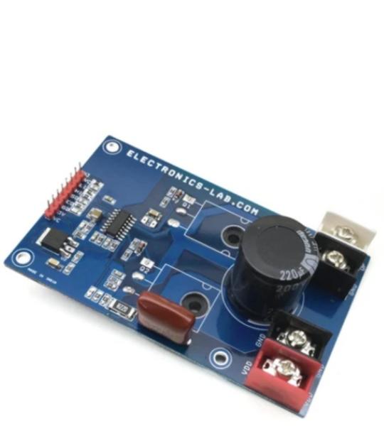
The project presented here is a versatile high voltage Half-Bridge with current feedback. The board is built using L6390 IC from ST Semiconductor. It is suitable for DC-DC converters, EHT drivers, induction heater drivers, battery chargers, LED drivers, DC motor speed controller and field-oriented control (FOC) motor driving application etc. The user can make a FOC Brushless motor driver with 3 of these units, Bidirectional Brushed DC motor can be controlled with 2 units. FDH3632 MOSFETs rated at 100V DC and 80A Current drive the output. Other High voltage and high current MOSFET can be used as per voltage and current requirements.
The project presented here is an Ignition coil driver featuring FAN1100-F085 ignition gate driver chip and IGBT. Chip is designed to directly drive an ignition IGBT and control the current and spark event of the coil. The coil current is controlled via the input signal pin. When the input is driven high, the output of the chip is enabled to turn on the IGBT and start charging the coil. Output sink current is programable using resistor R5 (RA). An input spike filter suppresses input signals of less than 13uS in duration. A Max Dwell timer is included in the chip which will turn off the IGBT if input stays active for longer than the programmable time. This time interval can be modified through an external capacitor on the CSSD pin. When the Max Dwell timer is exceeded, the CHIP will enter a Soft-Shut-Down mode (SSD) slowly dropping the collector current by lowering the gate drive to the IGBT thereby discharging the coil such as to inhibit a spark event. Once the soft shutdown operation has started, any transition on the input signal is ignored until after the completion of the soft shutdown function. Chip also limits the collector current of the IGBT during charging. This is done through the sense resistor R6 in the emitter leg of the ignition IGBT developing a signal input to the V-Sense pin of the chip.
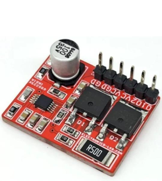
This is a simple low voltage push-pull voltage mode PWM controller based on LM5032 chip from TI. The board is build around LM5032 chip and two 100V 7A MOSFETs. It can be used in simple DC-DC converter, Tesla Coil Driver etc. The frequency can be changed with resistor R5. Resistor R7 play roll of current sense. Capacitor C4 configures the soft start function. Output is square wave open drain.
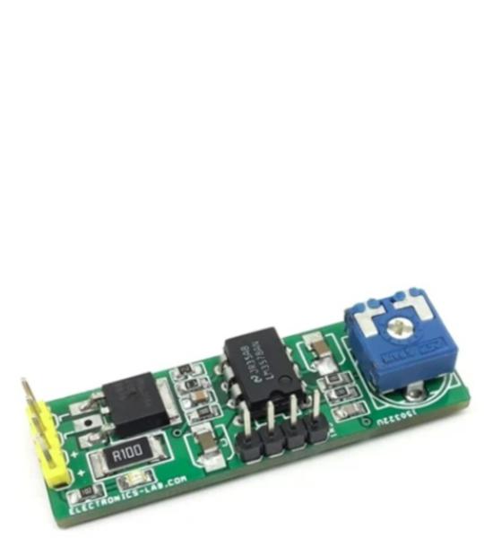
This Low-cost LED dimer project includes two main parts, an LM3578 chip, and a MOSFET. The LM3578 generates a PWM signal, and Q1 MOSFET helps to drive a high current LED. The project also includes current limit feature. Over current trigger point is set to 1.1A. LED intensity can be set using a board trimmer potentiometer. The compact and low-profile circuit occupies a very small area. PCB has the option to mount DIP8 IC or SOIC8 IC.
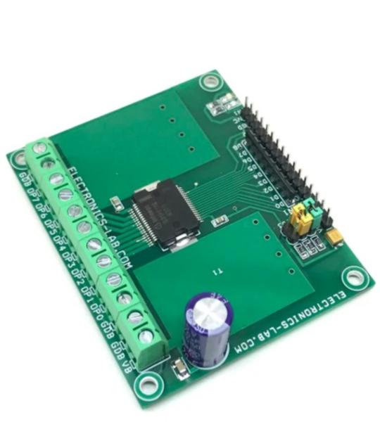
This project provides 8 fully protected and isolated high-side power switches that are able to handle current up to 625 mA. An 8-bit parallel microcontroller compatible interface allows connecting the inputs directly to a microcontroller or standalone circuit system. The input interface also supports direct control mode and is designed to operate with 3.3/5V CMOS compatible levels. The signal transfer from input to output side is realized by the integrated Coreless Transformer Technology. The board is designed for industrial applications such as process control and PLC to drive inductive, resistive, and capacitive loads like Relay, solenoid, lamps, heaters, piezo.
Cookie preferences