USD
 INR

Call Us Now
+91 9106756572
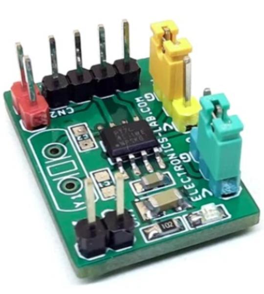
This is an easy-to-build project and it is the most cost-effective and high-performance frequency multiplier, which instigates analog phase lock loop techniques. The circuit provides high-quality, high-frequency output from lower frequency crystal or clock input. The project can be used as a crystal frequency oscillator, clock multiplier and frequency translation. Using phase-locked-loop (PLL) techniques, the device uses a standard fundamental mode, inexpensive crystal to produce an output clock up to 200Mhz. On-board jumpers are provided to select from nine different multiplication factors, which output many common frequencies. The device also has an output enable pin that tri-states the clock output when the enable pin is taken low. The chip is intended for clock generation and frequency translation with low output jitter.
This is an easy-to-build project and it is the most cost-effective and high-performance frequency multiplier, which instigates analog phase lock loop techniques. The circuit provides high-quality, high-frequency output from lower frequency crystal or clock input. The project can be used as a crystal frequency oscillator, clock multiplier and frequency translation. Using phase-locked-loop (PLL) techniques, the device uses a standard fundamental mode, inexpensive crystal to produce an output clock up to 200Mhz. On-board jumpers are provided to select from nine different multiplication factors, which output many common frequencies. The device also has an output enable pin that tri-states the clock output when the enable pin is taken low. The chip is intended for clock generation and frequency translation with low output jitter.
Refer to the table below for jumper settings to change the frequency multiplexing.
A parallel resonant, fundamental mode crystal should be used. The device crystal connections and capacitor connections are provided. These capacitors are used to adjust the stray capacitance of the board to match the nominally required crystal load capacitance. Because load capacitance can be only be increased in this trimming process. Crystal Capacitors, if needed, must be connected from each of the pins X1 and X2 to the ground.
The value (in pF) of these crystal capacitors should equal C-L x 2 in this equation, C-L=crystal capacitance in pF. Example: For a crystal with a 15pF load capacitance, each crystal capacitor would be 30pF.
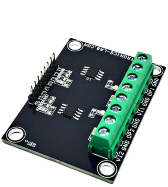
Module is a dual 12-bit PWM-to-voltage output DAC with high accuracy. The board is based on the LTC2644 chip. The LTC2644 measures the period and pulse width of the PWM input signals and updates the voltage output DACs after each corresponding PWM input rising edge. The DAC outputs update and settle to 12-bit accuracy within 8μs typically and are capable of sourcing and sinking up to 5mA (3V) or 10mA (5V), eliminating voltage ripple and replacing slow analog filters and buffer amplifiers. The circuit has a full-scale output of 2.5V using the 10ppm/°C internal reference. It can operate with an external reference, which sets the full-scale output equal to the external reference voltage. Each DAC enters a pin-selectable idle state when the PWM input is held unchanged for more than 60ms. The project operates from a single 2.7V to 5.5V supply and supports PWM input voltages from 1.71V to 5.5V. The PWM frequency can be any frequency between 30Hz and 6. 25kHz. The input level can be between 1.71V and 5.5V, set by a separate IOVCC pin. This project solves many problems associated with filtering a PWM signal to produce an analog voltage, producing a fast-settling, accurate analog voltage in response to a digital PWM input.
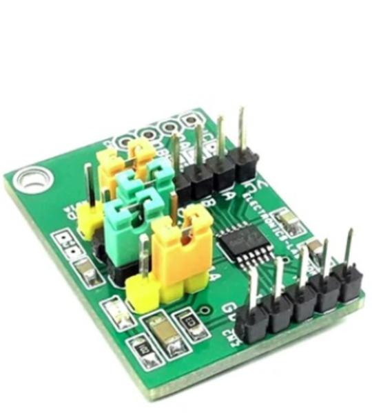
This is a two Channel high-side switch designed for automotive applications. It has a built-in overcurrent limit function, thermal shutdown protection function, open load detection function, low power output-OFF function etc. It also has a current sensing function of output load current.
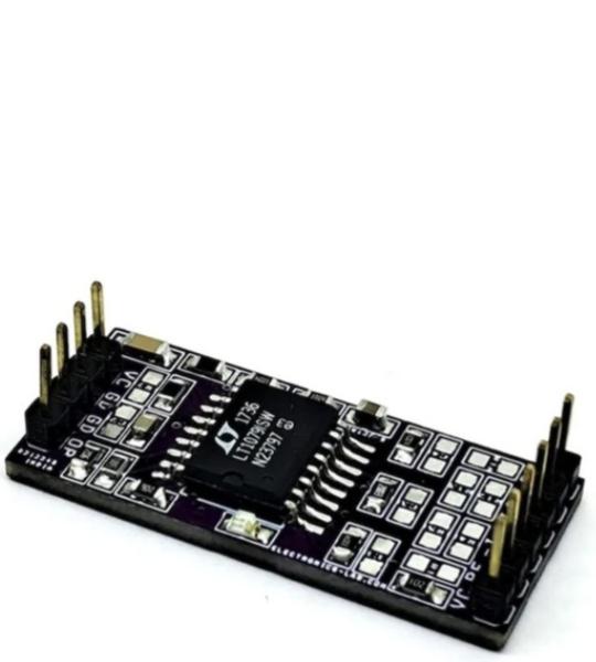
The LT1079 draws very little supply current while still delivering low offset voltage and low noise. This makes the module well-suited to battery-powered instrumentation and sensor front-ends where both precision and low power draw matter.
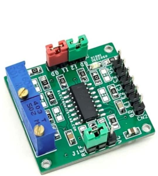
This is a versatile PWM generator module built around the TL494 PWM control chip. The flexible design allows for multiple component configurations to support various applications. Users can customize the module by installing only the components required for their specific application while leaving out unnecessary components.
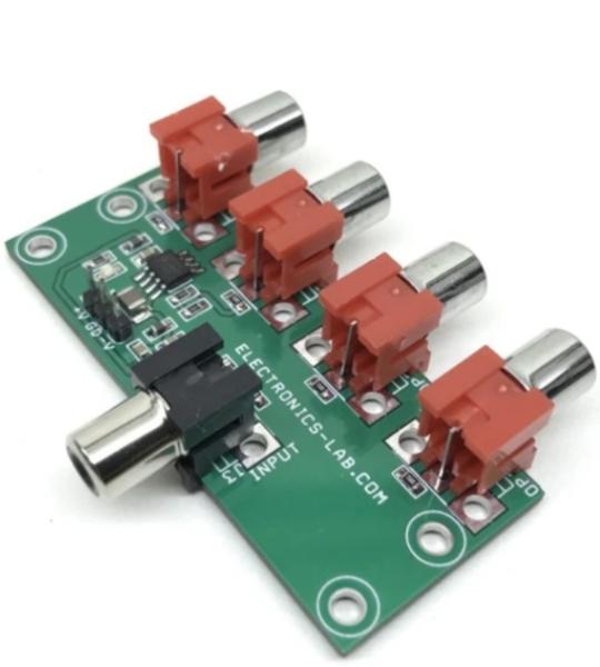
This is a low-cost video distribution amplifier capable of driving up to four video lines. The amplifier is configured with a non-inverting gain of 2. The input video source is terminated in 75 Ohms and is applied to the high impedance non-inverting input. Each output line is connected to the op-amp’s output via 75 Ohms series back termination resistor for proper cable termination. The termination resistor at the other end of the lines divides the output signal by 2, which is compensated by the gain of 2 of the op-amp. The project is built using AD8010 op-amp which is optimized for this specific function of providing excellent video performance in driving multiple video loads in parallel. Significant power is saved and heat sinking is greatly simplified because of the ability of the AD8010 to obtain this performance when running on ±5 V supply. Circuit provides 46dB of output-to-output isolation at 5Mhz driving back terminated 75 Ohms cable. Ferrite beads and high-value ceramic capacitors are used on the power supply input to reduce the noise.
Cookie preferences