USD
 INR

Call Us Now
+91 9106756572
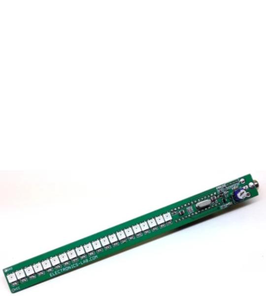
This is a fun-loving project based on the Arduino platform. The project creates color light effects with sound level sense by an onboard condenser microphone. The project consists 20 x WS2812B RGB LEDs, an Atmega328 micro-controller, condenser microphone along with pre-amplifier, RCA connector, and trimmer potentiometer to direct feed audio. The project can be used in fun parties, disco parties etc. Just power the board and RGB LEDs will create different colors as per sound level. Board has the option of direct audio input or sound sense by the microphone, users may change the Arduino example code as per requirement or write their own code.
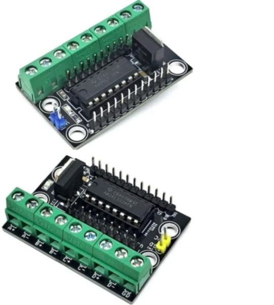
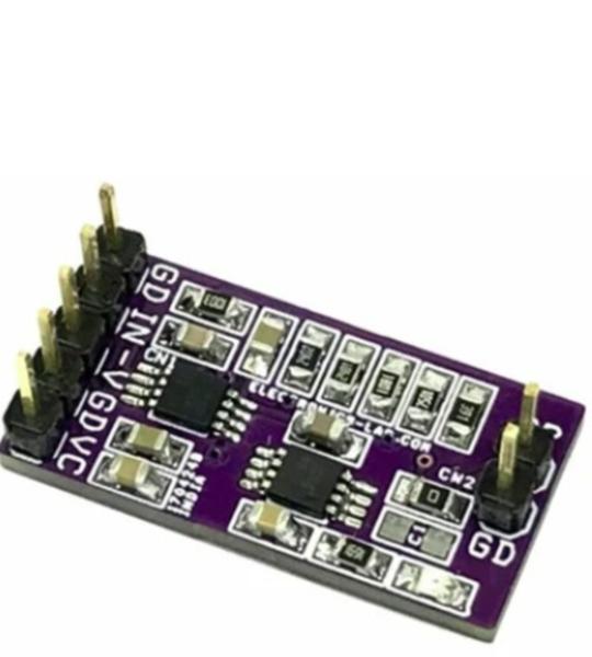
This Quadruple Differential Line Driver module provides four independent differential output channels for driving balanced transmission lines in industrial and embedded applications. Built around the Texas Instruments AM26LS31 IC in a DIP-16 package, the module meets TIA/EIA-422-B and ITU standards. It delivers high-current 3-state outputs capable of driving twisted-pair or parallel-wire transmission paths. In my next project, I will show you how to build the complementary four-channel RS-422 differential line receiver.
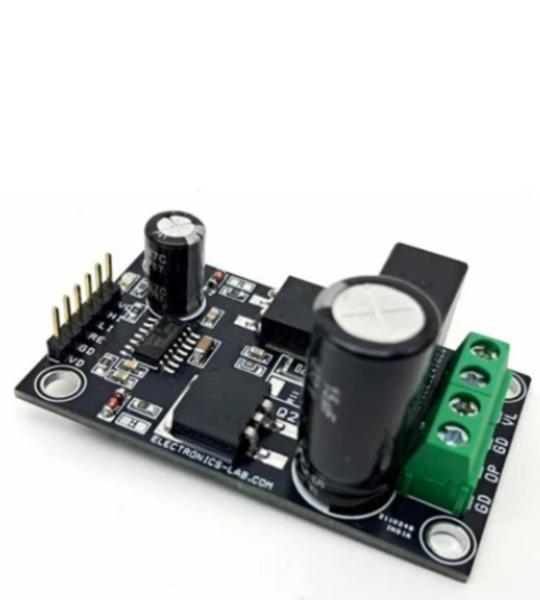
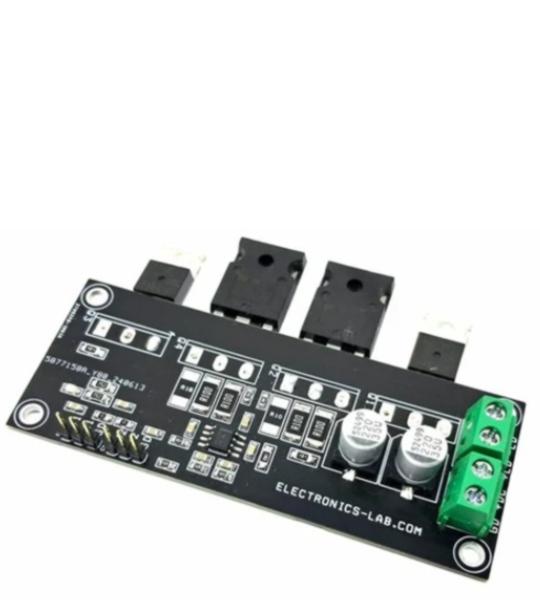
The Half-Bridge Driver project presented here is designed to support load power supplies of up to 400V DC. The board features the IRS2890DS Half-Bridge Gate Driver IC, which is paired with two IGBTs rated at 8A/650V, conveniently mounted on the board. The board features overcurrent shutdown. Barrier Terminal Blocks provided for load and input supply.
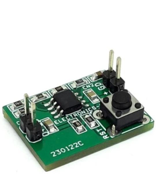
A rechargeable battery’s load should be disconnected at the point of complete discharge, to avoid a further (deep) discharge that can shorten its life or destroy it. Because a battery’s terminal voltage recovers when you disconnect the load, you can’t simply disconnect the load when the terminal voltage dips below the established threshold and then re-connect it when the voltage returns above that threshold. Such action may produce chatter in the disconnect switch. The project shown here is a complete solution to this problem.
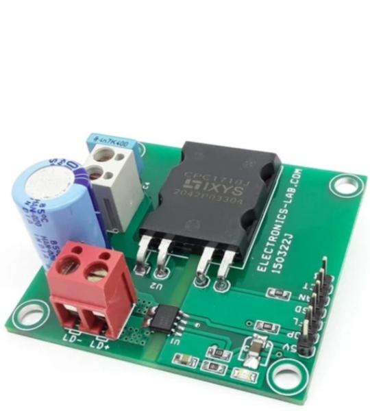
Optically Coupled Power MOSFET Relay with Galvanically Isolated Current Monitor Output
This project employs CPC1718J 100V Single-Pole, Normally Open DC-Only Power Relay and ACS71240 Galvanically Isolated Current Sensor IC with Common-Mode Field Rejection and Overcurrent Detection. The board can be used for applications such as industrial controls, motor control, robotics, and electronics switching. The relay is normally open and requires a 3.3V to 5V input signal to operate with a maximum operating load power supply of 100V DC, and load up to 6.75A without a heatsink and 17.5A with a heatsink
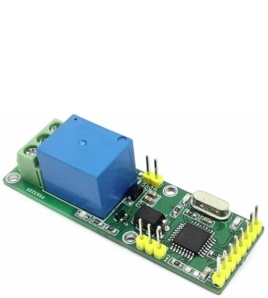
This RC Relay project enables control of large current devices using a Radio Control (RC) System. This RC switch converts hobby radio control (RC) pulses to control the on/off state of the Relay. On board LED indicates the output. The board is Arduino compatible and the example code can be modified as per user requirements. The relay ON/OFF threshold can be set as per user requirements. The Arduino sample code enables momentary ON/OFF control of the relay, but this can be modified for Latch output. The relay can handle a load up to 7A – 30V DC or 7 Amps 230AC Loads such as bulbs, LEDs, motors, fans, heaters etc. The project can be connected to an unused RC channel. It operates with 5V DC and draws 60mA current when the relay is ON. 3 Pin male header helps the user to connect the RC receiver. The project is Arduino compatible and can be programmed using Arduino IDE with the help of an onboard programming connector. The project consists of an Atmega328 microcontroller, programming/bootloader connector, relay, BC847 BJT transistor to drive the relay, freewheel diode for protection from the relay, and U2 PC817 provides isolation between the microcontroller and relay. D1 LED indicates output, D3 LED power LED. connector CN2 relay switch connection, connector CN1 5V supply input.
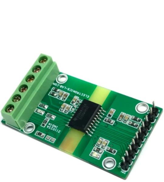
The product presented here is a galvanically isolated differential line transceiver with a built-in isolated DC-DC converter for TIA/EIA RS-485 and RS-422 applications. Both signal and power paths are isolated per UL1577 and are qualified for reinforced isolation per VDE, CSA, and CQC. The low-emissions, isolated DC/DC converter ensures the final system is capable of meeting CISPR 32 radiated emissions limit lines with just two ferrites’ beads. The project is ideal for long-distance communications. Isolation breaks the ground loop between the communicating nodes, allowing for a much larger common-mode voltage range.
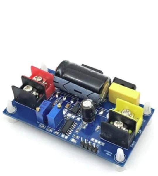
The high-voltage half-bridge board features a 2ED2184 half-bridge gate driver, 2 x IKW20N60H3FKSA1-ND IGBTs, and an SG3525 PWM signal generator. This board is designed to support bus supplies of up to 400V DC, PWM frequency up to 6.5Khz and adjustable duty cycle range 2% to 98% making it suitable for a wide range of applications, including: Refrigeration systems DC-DC converters AC to DC converters Electric vehicle (EV) chargers High-power LED and HID lighting systems Induction heating systems Features Load Power Supply 400V DC Load Current 2-5Amps Power Supply Logic Gate Driver 12-15V DC On Board Power LED On Board Multiturn Potentiometer for Frequency/PWM Adjust PWM Signal Adjustable 2% to 98% Frequency Adjustable 500Hz to 6.5Khz Barrier Terminal Blocks for Load and Load Power Input On Board 100uF/450VDC Bus Capacitor PCB Mounting Holes 4 x 4 mm PCB Dimensions 79.53 x 43.50 mm The onboard SG3525 chip provides adjustable frequency and PWM (Pulse Width Modulation) signal generation, allowing users to customize the output to their specific needs.
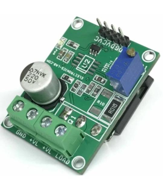
This voltage-to-current (V-I) converter delivers a well-regulated current to a load. The circuit accepts an adjustable input voltage from Trimmer potentiometer PR1 and converts it to an output current from 0A to 1A. The current is regulated by feeding the voltage across a low-side, current-sense resistor R9 back to the OPAMP. The output Darlington pair allows for higher current gain. Feedback components R8 and C6 provide frequency compensation to ensure the stability of the circuit during transients. They also help reduce noise. R8 provides a DC feedback path directly at the current setting resistor, R9, and C1 provide a high-frequency feedback path that bypasses the NPN pair.
This design is intended to translate a small unipolar signal to a wide bipolar signal. A common application is to translate a 0 to 5V DAC output to a ±10V bipolar signal. All resistors are 1% but it is advisable to select 0.1% 20 ppm/°C resistors for good gain, offset accuracy, and drift tolerance. A calibration at room temperature can be done to minimize the gain error, but gain drift can only be reduced by minimizing the resistor drift (choosing resistors with TC ≤ 20 ppm/°C). The project is built using OPA2206 Precision, bipolar, e‑trim OPAMP. REF5050 provides 5V reference voltage to OPAMP. The board works with a dual ±15V DC Power Supply.
This low-side voltage-to-current (V-I) converter delivers a well-regulated current to a load. The circuit accepts an input voltage from 0V to 3V and converts it to a current from 0A to 6A (combined). The current is accurately regulated by feeding back the voltage drop across a low-side current-sense resistor (R8, R9 + R16, R17) to the OPAMP. Resistor divider (R4 and R5 + R12 and R13) is implemented to limit the maximum voltage at the non-inverting input, Vin, and sense resistor, (R8, R9 + R16, R17), at full-scale. Using a Darlington BJT reduces the output current requirement for the OPAMP. Feedback components R6+R13, R7+R15, and C5+C6 provide compensation to ensure stability. R6+R13 isolates the input capacitance of the bipolar junction transistor (BJT) R7+R15 provides a DC feedback path directly at the current setting resistor (R8, R9 + R16, R17), and C5+C6 provides a high-frequency feedback path that bypass the BJT.
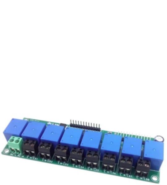
This is an SPI Interface multichannel relay board for high voltage AC or low voltage DC loads. It is ideal for controlling LEDs lights, coffee machines, fans, pumps, or other high-voltage electrical appliances. The board also breaks out the SPI header, so controlling other boards is still possible. Each relay can handle current up to 7A @ 250V AC/30V DC. This 8 x channel board is mainly designed for AC loads, but it can also drive DC loads, screw terminals on each channel enable the easy interface of the AC load, and each point is marked as AC-Live and AC Neutral. Refer to the connection diagram for the interface. The project consists of 8 x 12V relays with load capacity 7A @ 250V AC, ULN2803 8 channel relay driver, 74HC595 SPI to 8 output, 5V regulator 7805, power LED, screw terminals for loads and AC input, header connector for SPI input and output.
Cookie preferences