USD
 INR

Call Us Now
+91 9106756572
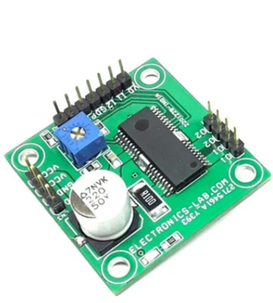
This is a powerful yet small size low profile brushed DC motor drive system with a few key features like adjustable constant current control, direction control, brake controls, Alert output, PWM for speed control etc. BD63130AFM chip is the heart of the project which is an H-bridge motor driver for the DC brush motor. This driver can facilitate low power consumption by direct PWM or PWM constant current control. There are various built-in protection circuits in this IC. It is possible to output an abnormal detection signal for Wired-OR that notifies each protection circuit operation, and this contributes to set high reliability.
This is an advanced Motion module providing a fully featured, high-performance inverter output stage for AC induction, BLDC and PMSM motors such as refrigerators, fans, and pumps. This module is based on NFA50460 chip which integrates the optimized gate drive of the built−in IGBTs (FS4 RC IGBT technology) to minimize EMI and losses, while also providing multiple on−module protection features including under−voltage lockouts and thermal monitoring. The built−in high-speed Driver IC requires only a single supply voltage and translates the incoming logic−level gate inputs to the high voltage, high current drive signals required to properly drive the module’s internal IGBTs. Separate open emitter IGBT terminals are available for each phase to support the widest variety of control algorithms. Heatsink is a must for the IC before conducting any test.
Driving a 3-phase brushless DC motor is very easy with this product. It is a simple and easy-to-build project that requires only a few external components. The circuit is based on AMT49400 IC which is an advanced 3-phase, Sensorless, brushless DC (BLDC) motor driver with integrated power MOSFETs. The chip includes the field-oriented control (FOC) algorithm which is fully integrated to achieve the best efficiency and acoustic noise performance. The motor speed is controlled by applying a duty cycle signal to the PWM input. Users may use Arduino, microcontroller, or discrete circuit to generate PWM for the speed controller. It is a hassle-free easy to use board, just connect the 3 phase brushless motor, connect the power supply and feed PWM to control the speed of the motor. This project is the best choice to drive a FAN motor, small pumps, and brushless toy motors, etc. The circuit also outputs FG speed output information which can be used for feedback. Chip also has a short circuit protection feature that prevents damage to the IC or motor. Any of these three conditions: phase to GND, phase to VBB, and phase to phase will trigger the OCP event, and the AMT49400 will stop supplying current to the motor immediately. The OCP can recover after a power cycle or PWM demand cycle. If the OCP restart mode (EEPROM setting) is “time”, the OCP can recover after 5 seconds.
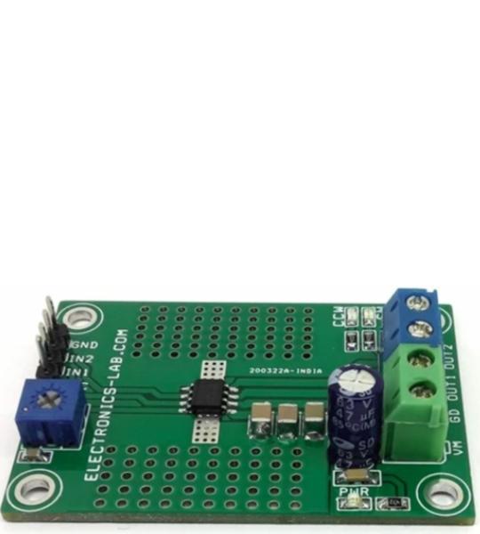
The highly efficient DC brushed motor driver including an onboard shunt resistor for current regulation presented here is built using the DRV8251 chip. The operating supply voltage range of the project is 4.5V to 48V DC and the default output current capability is 2.1A. A trimmer potentiometer PR1 is provided to adjust the current regulation threshold. The device includes under-voltage lockout (UVLO), Latched overcurrent protection (OCP), and thermal shutdown (TSD). Output is disabled and latched when over current/stall current condition occurs. For direction control of the motor use IN1 and IN2 as logic inputs and for speed control these inputs can be connected to a PWM source with duty cycle 0 to 100% and frequency 20Khz.
This is a 3-Phase Inverter Driver project designed for Low Power AC Motor. The FSB50450AS chip is the heart of the project. A compact inverter project is ideal for small power motors such as fans and pumps. An H-bridge configuration can also be created for low-current high-voltage brushed DC motors. The Inverter project supports loads up to 1.5A. The DC power supply voltage is up to 400V DC. The project operates with 6 x PWM signals. Parameters for bootstrap circuit elements are dependent on the PWM algorithm. For 15 kHz switching frequency, Bootstrap capacitors C1, C2, and C3 value is 1uF. Resistor R1, R2, R3, R4, R6, R7 and capacitor C4, C5, C6, C7, C8, C9 prevent improper signal due to surge-noise. Over-current or fault detection circuit is created using comparator CN5 – LMV7239 and shunt resistor R5. The output of LMV7239 is normally high and goes low when an over-current condition occurs. So, the CS pin goes low when the current goes above the threshold level. ATS pin is provided to monitor the temperature of the IPM chip. Heatsink is a must for this IPM module. Adhesive material with high thermal conductivity, such as Loctite 384, can be used to fix the heat sink on the top surface of the chip. Refer to the heatsink installation diagram.
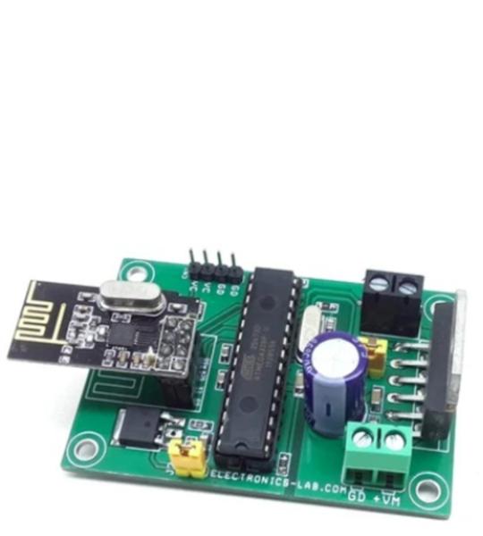
This is Arduino compatible hardware that can control a single DC motor speed, direction, and brake using an RF remote control. The project is based on an ATMEGA328 microcontroller, H-Bridge DC motor driver chip LM18201, NRF24L01 RF module, 5V Regulator, 3.3V regulator and other components. This board can drive a DC Motor up to 24V DC with a load current up to 3A. Arduino pin configuration details are provided below, the user may write their own code and use this hardware. The ATMEGA328 is the heart of the project, the LMD18201 chip drives the motor, LM317-ADJ provides 5V to the microcontroller, LM1117 3.3V regulator power the 3.3V to NRF24L01.
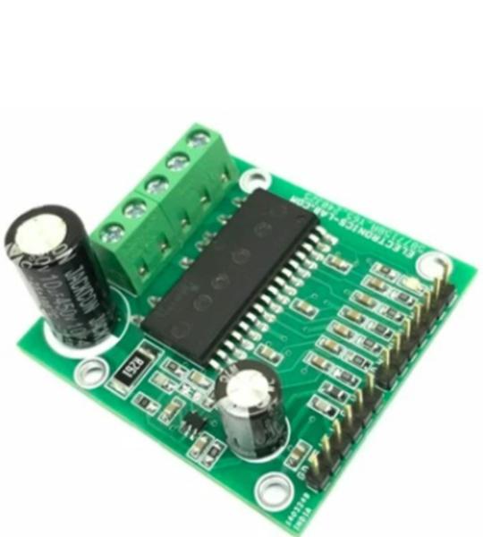
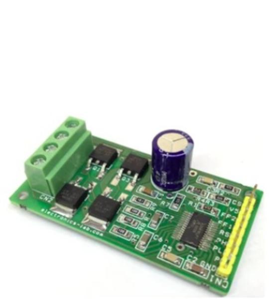
This tiny board is designed to drive a bidirectional DC brushed motor of large current. DC supply is up to 50V DC. A3941 gate driver IC and 4X N Channel Mosfet IRLR024 used as H-Bridge. The project can handle a load of up to 10A. Screw terminals are provided to connect the load and load supply, and 9 Pin header connector is provided for easy interface with the microcontroller. An on board, shunt resistor provides current feedback.
The A3941 is a full-bridge controller for use with external N-channel power MOSFETs and is specifically designed for automotive applications with high-power inductive loads, such as brush DC motors. A unique charge pump regulator provides full (>10 V) gate drive for battery voltages down to 7 V and allows the A3941 to operate with a reduced gate drive, down to 5.5 V. A bootstrap capacitor is used to provide the above-battery supply voltage required for N-channel MOSFETs. An internal charge pump for the high-side drive allows DC (100% duty cycle) operation.
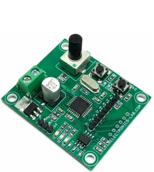
This is an RC servo controller board that allows users to record RC servo motor movement and playback it back with precision. There is an onboard potentiometer to control the RC servo up to 180 degrees. It allows you to record the movement of one servo, a few seconds in duration. Servo movement can be mimicked using the onboard potentiometer. Servo movement data is stored onboard the EEPROM memory chip. The project is Arduino compatible and can be modified to work as a data logger and other applications that require EEPROM and SD Card data logs.
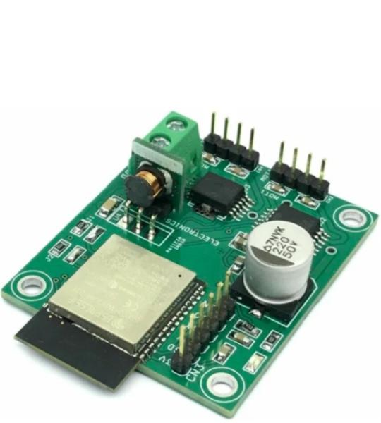
This wireless robot car controller board is built using an ESP32 BT/Wi-Fi module, 2 x H-Bridges, 3.3V regulator. It also includes an ESP32 programming connector, power LED, screw terminal connector for the power supply, header connector for motors, and high-value capacitors on the DC supply for smooth motor operations. The operating power supply is 8V to 24V DC. The project has two H-brides and each can drive 2.5A continues. The board is suitable for small and medium-sized robot cars. It is an open-source hardware project that can be programmed as per requirement. ESP32 I/O details are available in descriptions. ESP32 supports Bluetooth connectivity and the robot car can be controlled using a small phone, Laptop, or Tablet. The project was built using an ESP32-Wroom processor and this chip supports Bluetooth and Wi-Fi connectivity.
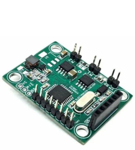
This project presents a robot car controller that utilizes a Bluetooth wireless controller, allowing users to control the small robot car using a smartphone and an Android app. The system consists of an Arduino microcontroller (ATMEGA328), an HC-05 Bluetooth module, two BD6211 H-Bridge motor drivers, and an onboard DC-DC converter that provides 5V power to the microcontroller and related circuitry. The circuit operates on a 6V DC battery, making it an ideal choice for small to medium-sized tank and robot car applications. Each H-Bridge channel can handle currents up to 1A.
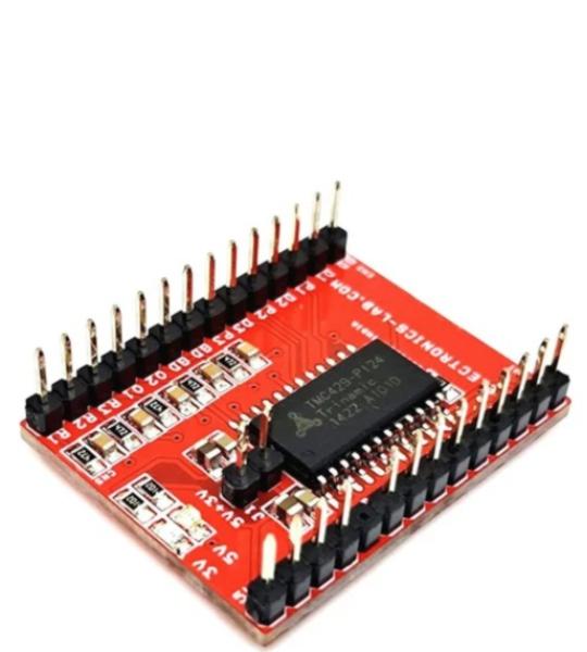
This TMC429 Breakout Board is a versatile motion control solution that enables users to create sophisticated three-axis motion control systems. This board interfaces with the TMC429 chip through SPI communication and provides 3-axis step/direction output signals along with limit switch inputs.
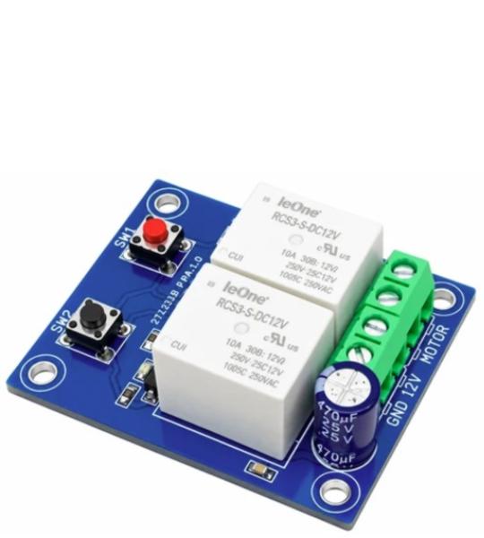
The project presented here is a low-cost easy to use DC brushed motor direction controller with fast-brake, the project was built using two 12V Relays, 2 x BJT transistors, and 2 x tactile switches. The two LEDs are provided to display the motor direction, 2 tactile switch controls the direction of the motor.
Cookie preferences