USD
 INR

Call Us Now
+91 9106756572
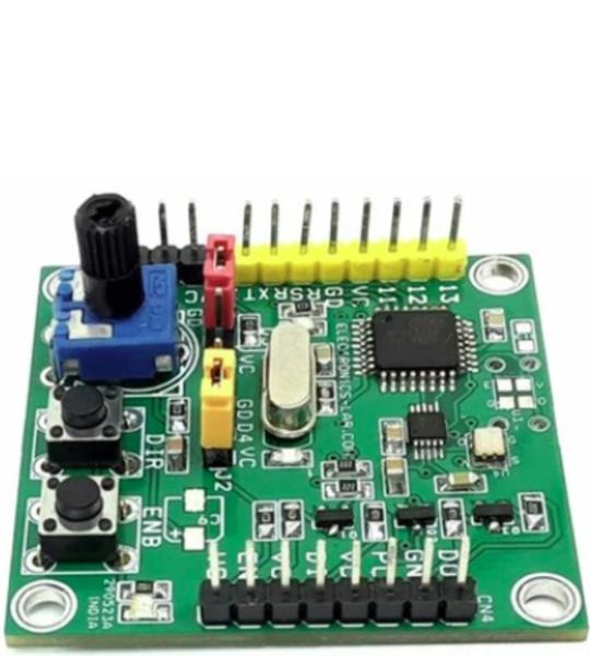
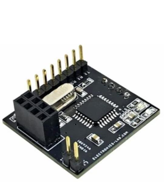
A programmable pulse generator is a very useful tool for stepper, BLDC, and AC servo drivers. Various stepper and servo drivers work with step and direction inputs. This project is the right solution to drive such drivers since it can provide a high-frequency output which is important for most AC servo drivers. The project provides a jitter-free high-frequency pulse, direction, and enable signal. The output frequency can be configured up to 12 MHz since the project is Arduino-compatible. All outputs are open collector types (5V). 2 x tactile switches are provided to set the direction and enable. An onboard trimmer potentiometer is provided to adjust the step frequency.
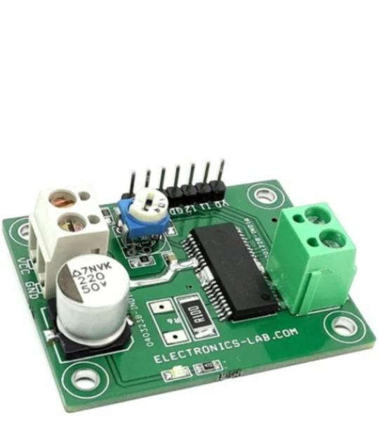
This is a powerful yet small-size and low-profile brushed DC motor drive system, with key features like adjustable constant current control, direction control, brake controls, Alert output, PWM for speed control, etc. The BD63150AFM chip is the heart of the project which is one H-bridge motor driver for DC brush motors. This board enables low power consumption by direct PWM or PWM constant current control. Built-in protection circuits in this IC are present. It is possible to output an abnormal detection signal for Wired-OR that notifies each protection circuit operation, and this contributes to the high reliability of this board.
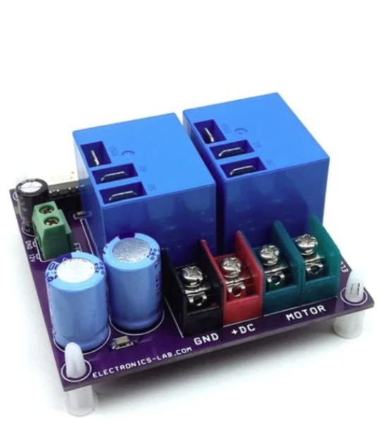
The project presented here is a low-cost solution to control high power brushed DC motor speed and direction. Traditional DC motor controllers are based on solid-state circuitry known as H-Bridge. Here we have made an H-bridge configuration using high current 2 x relays which can handle high voltage as well as high current. Additional MOSFETs are used to control the speed of motor. These MOSFETs can be removed in case of only direction control required, short the Drain and source pin of MOSFETs. The project requires 3 control input signals, all inputs are optically isolated to prevent noise and high voltage going in to logic circuitry. A large-size heatsink is a must on MOSFET.
This is a pulse generator for a stepper motor driver using a joystick. It is a board that contains an Arduino-compatible microcontroller and circuitry for controlling up to 2-channel (2-axis) stepper motors. The board has multiple options to develop stepper motor-related control systems, from a 2-axis analog joystick to a trimmer potentiometer to a 7-channel open collector TTL output to interface stepper drivers with optocoupler inputs, etc.
This Wi-Fi Stepper Motor Driver enables remote control of a bipolar stepper motor over a wireless network. The project is based on the ESP32 Wi-Fi microcontroller and the BD63731EFV stepper motor driver IC, providing a compact and reliable solution for motion control applications.
The driver operates from a 24 VDC power supply and is capable of driving bipolar stepper motors with output currents of up to 3A. The BD63731EFV supports multiple micro-stepping modes, allowing smooth and precise motor operation while reducing vibration and audible noise.
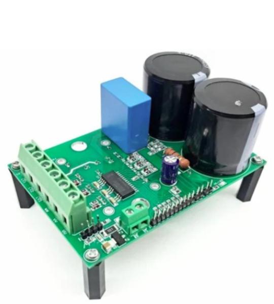
The power board described here is designed for motor applications, featuring the 6ED2230S12T gate driver IC and FP15R12W1T4 IPM power module from Infineon. It provides an AC input and a 3-phase power output, with a single emitter shunt for current sensing and a voltage divider for DC-link voltage measurement. The board includes an LM1117S33 linear regulator to generate 3.3V from the 15V VCC, which is used to supply the gate driver IC and other related circuits.
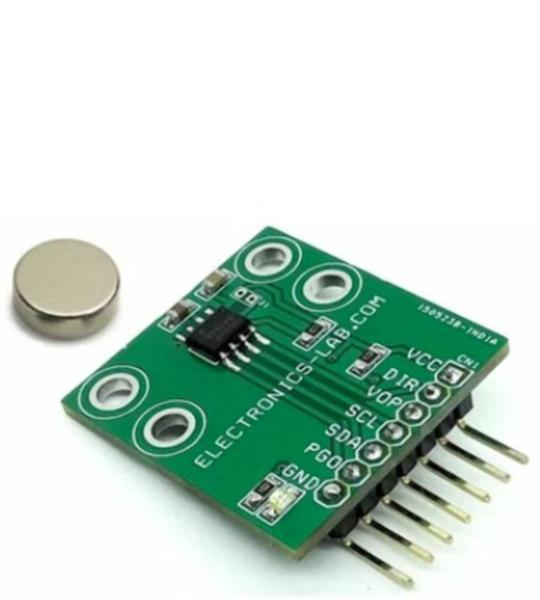
This is an easy-to-program magnetic rotary position sensor with high-resolution 12-bit analog or PWM output. This contactless system measures the absolute angle of a diametric magnetized on-axis magnet. The project is designed for contactless potentiometer applications and its robust design eliminates the influence of any homogenous external stray magnetic fields. The industry-standard I²C interface supports simple user programming of non-volatile parameters without requiring a dedicated programmer. By default, the output represents a range from 0 to 360 degrees. It is also possible to define a smaller range to the output by programming a zero angle (start position) and a maximum angle (stop position). The AS5600 is also equipped with a smart low-power mode feature to automatically reduce power consumption. An input pin (DIR) selects the polarity of the output with regard to rotation direction. If DIR is connected to the ground, the output value increases with clockwise rotation. If DIR is connected to VDD, the output value increases with counterclockwise rotation.
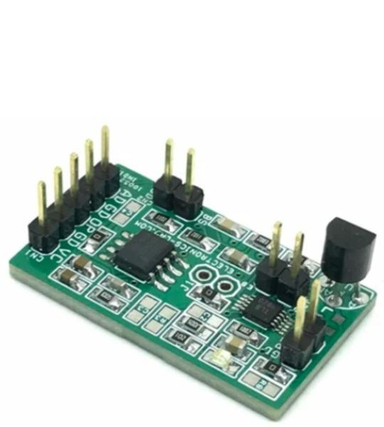
This sensor board provides frequency output as per relative humidity value. The project is based on a unique capacitive cell, this relative humidity sensor is designed for high volume, cost-sensitive applications such as office automation, automotive cabin air control, home appliances, and industrial process control systems. It is also useful in all applications where humidity compensation is needed. The circuit is built using a low-cost NE555 timer as an astable generator, humidity sensor MK1 acts as a variable capacitor and is connected to the TRIG and THRES pin. Pin 7 is used as a short circuit pin for resistor R3. The HS1101LF equivalent capacitor is charged through R2, R3, and PR1 is set the threshold voltage (approximately 0.67Vcc) and discharged through R2 only to the trigger level (approximately 0.33Vcc) since R3 is shortened to the ground by pin 7. Since the charge and discharge of the sensor run through two different resistors, R2 and R3, the duty cycle is determined by the following formulas.
This project is the receiving end of a Wireless Humidity and Temperature monitoring system. The receiver unit is built around an Arduino microcontroller, utilizing the ATMEGA328 chip, which provides a reliable and efficient processing platform. The NRF24L01 transceiver module is used to receive data from the corresponding wireless sensor, while a 0.96-inch I2C OLED display is employed to show the received temperature and humidity values in real time.
This isolated single-supply bidirectional current sensing project can accurately measure load currents from –2A to 2A. The linear range of the input is from –250mV to 250mV with a differential output range of –2.05V to 2.05V. The gain of the circuit is fixed at 8.2V/V. The project is based on AMC3301 chip which has a fully integrated, isolated DC/DC converter that allows single-supply operation from the low side of the device. The integrated DC-DC converter saves lots of board space. The reinforced capacitive isolation barrier is certified according to VDE V 0884-11 and UL1577 and supports a working voltage of up to 1.2 kVRMS. The isolation barrier separates parts of the system that operate on different common-mode voltage levels and protects the low-voltage side from hazardous voltages and damage. Output is fully isolated from the input and optimized for high voltage interface. The project provides differential output for easy interface with ADC. Operating Power supply 5V DC.
This is a simple Proportional, Integral (PI) temperature control amplifier. A complete thermoelectric cooler (TEC) controller can be created using this PI amplifier and OPA569 Power Op-Amp or other output amplifiers such as DRV591, DRV592 and DRV593. Proportional-integrator compensation is simpler to adjust and often provides an adequate thermal transient response to the TEC driver amplifiers. The project consists INA330 chip and OPA2340 OPAMP. The INA330 provides thermistor excitation and generates an output voltage proportional to the difference in resistances applied to the inputs. OPA2340 is used to create the PI closed Loop.
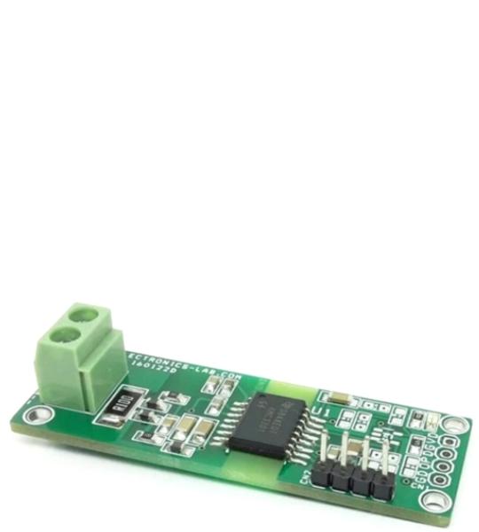
This is anUltra Precision Zero Drift High-Side Current-Sense Amplifier module, featuring the LTC6102 chip and it is designed to amplify the voltage drop across an on-board current-sense resistor, providing a precise unipolar output voltage proportional to the load current. The circuit incorporates a scaling resistor, R4, which programs the gain of the circuit to 33.3V/V. Notably, the LTC6102 enables current measurements on supplies ranging from 4V to 60V.
Cookie preferences