USD
 INR

Call Us Now
+91 9106756572
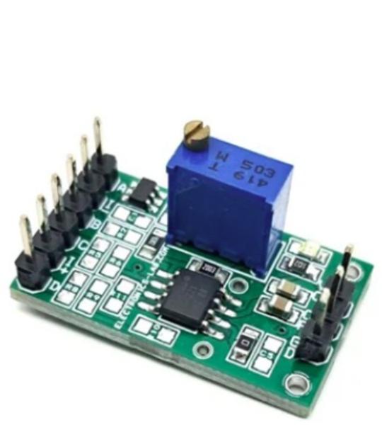
This is a precision instrumentation amplifier board based on the INA122 chip, designed for accurate and low-noise differential signal acquisition. Here are the key features and specifications.
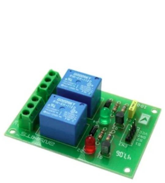
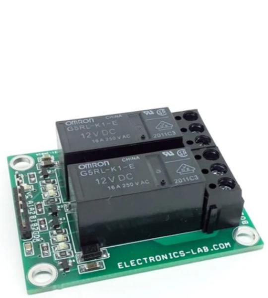
2 channel Relay driver project can be controlled by feeding 2-12V trigger voltage, Very useful project for application like Micro-Controller based projects, Remote controller, Lamp on Off, and any circuits which required isolated high current and high voltage switching by applying any TTL or CMOS level voltage. Two LED works as operation indicator while in , 3 pins screw terminals to connect load and provides both normally open and normally closed switching.
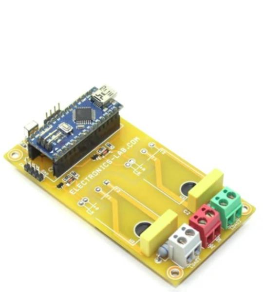
This is a two-channel infrared remote ON/OFF switch that can be used to control home appliances, Lights, Fans, Water Pumps, Aquarium pumps, Ovens, Heaters, etc. This open-source project contains 2 x SSR (Solid State Relay), Arduino Nano, and TSOP1838 infrared receiver, keeping safety in mind, optically isolated SSR (Solid State Relay) is used to have isolation between high voltage AC circuitry and Arduino Nano. The operation of the circuit is pretty simple, TSOP1838/TSOP38238 IR Sensor receives the infrared signal from IR remote, Arduino Nano decodes the IR signal which is connected to digital pin D2 and provides latch outputs on digital pins D5, and D6 in respect to IR code received from IR remote. These two digital outputs D5, D6 drive the SSR using 2 x BC847 BJT transistors. CPC1998J optically isolated solid-state relays from IXYS Integrated Circuits drive the AC loads. We have tested this board with 500W/230V AC lamps, however, the load capacity of SSR is 20A. A snubber circuit is provided across the SSR-Traic which helps driving inductive loads. Heat-sink on SSR is not required for loads up to 5A, but for higher load, it is advisable to mount a heatsink on SSR.
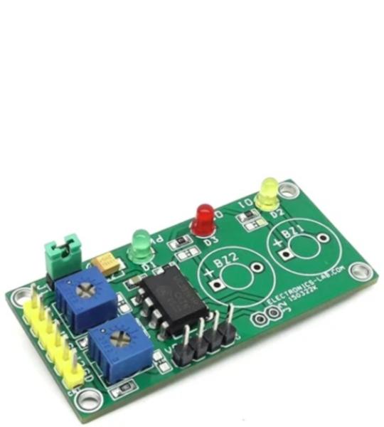
This module built using MC33161 IC, which is a universal voltage monitor intended to be used in a wide variety of voltage sensing applications. The project offers an economical solution for positive and negative voltage detection. The circuit consists of two comparator channels each with hysteresis, a unique Mode Select Input for channel programming, a pinned out 2.54 V reference, and two open collector outputs installed with LED for visual alert for under-voltage and over-voltage situations. The project is configured for a 5V supply by default. It provides a visual indication when supply is lower the 5V and over 5V. Yellow LED indicates undervoltage and Red LED indicates overvoltage. Trimmer potentiometers PR1 and PR2 were provided to adjust the Undervoltage and Overvoltage range. Both inputs can be used as independent or combined (Single Input)
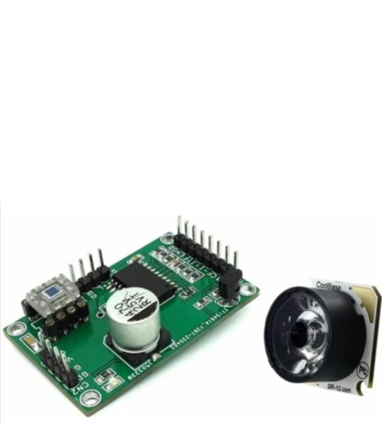
This is a is a precision closed-loop LED driver that provides very accurate constant light and can be used for photography, scientific research, and other applications that require an accurate light source. The project consists of light sensor OPT101 and OPA569 power OPAMP. OPT101 converts light into voltage, and OPA569 is used as an adjustable linear current source that controls the flow of current through the power LED. Installation of the Power LED and OPT101 Sensor is shown in the figure below. The overcurrent limit of LED is set to 1A using resistor R4. LM336 provides an accurate voltage reference to OPAMP which is 0.5V. The circuit works in a closed loop. At power ON, the LED light reflects to the sensor, and OPT101 provides the voltage output as the light level falls on the sensor, this voltage is fed to power op-amp, and op-amp compares the input voltage from OPT101 and reference voltage 0.5V. If there is an error, the op-amp controls the current of the LED to match the disparity between the output and input. This way light level is maintained and this is constant. It is important to have proper housing for the sensor so external/ambient light should not fall on the sensor, otherwise constant light will not be maintained.
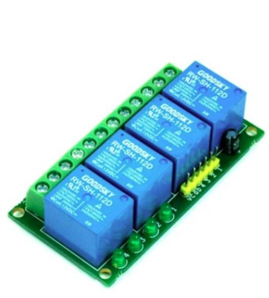
Quad Channel Relay Board is a simple and convenient way to interface 4 relays for switching application in your project. Features Input supply 12 VDC @ 170 mA Output four SPDT relay Relay specification 5 A @ 230 VAC Trigger level 2 ~ 5 VDC Berg pins for connecting power and trigger voltage LED on each channel indicates relay status Power Battery Terminal (PBT) for easy relay output and aux power connection Four mounting holes of 3.2 mm each PCB dimensions 88 mm x 68 mm 4 Channel Relay Board
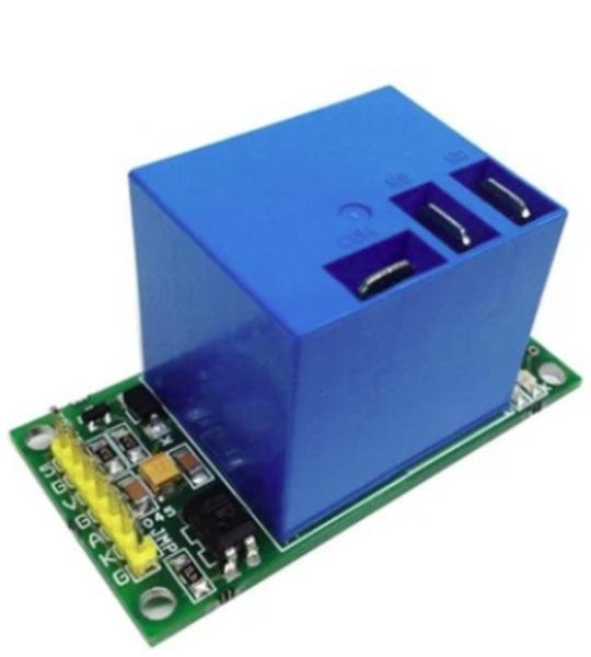
This is a large current Relay module with single pole double throw switch which provides normally closed and normally open operations. The Relay is the most common used module in application such as home automation, industrial automation, and machine on/off. Sometimes you need to control large current such as the fans, lights, water heaters, room heaters, Air-conditioning, vacuum pumps That is what this Large Current Relay Module can be helpful to drive such high current load with just TTL signal. Easy interface with embedded systems and micro-controllers.
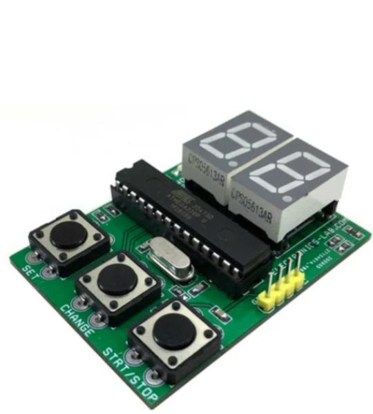
This is an open source 2-digit 7 segment Arduino compatible display board. It can used in many applications that require 2-digit display and switches inputs. Possible application of this board is a 2-digit counter, 2-digit countdown timer, token display, score board etc. 2 x 7 segment 0.56-inch Common cathode displays are used in multiplexing mode. Refer to the connection table to check connections between display segments and Atmega328 chip. A led connected to A4 pin of IC is used as indicator LED. All 3 switches have pull-up resistors of 10Kohms, 220E ohms series resistors used between I/O pin of Atmega328 chip and display segments.
4 Channel Relay Board is a simple and convenient way to interface 4 relays for switching application in your project. Very compact design that can fit in small area, mainly this board is made for low voltage applications.
This is a Smart Dual Coil Latching Relay that can control the ON/OFF power of a device by applying a short voltage pulse to Input 1 and Input 2. This project is helpful in low-power applications since the coil is not powered all the time, it only requires a short voltage pulse. Relay Coil also remains in that position even if the power is disconnected. Polarized, bi-stable, latching relays are utilized in many kinds of electronic equipment and diverse applications. These relays usually employ two coils, one to move the relay contacts(s) from the open to close position and another coil to move the contacts(s) from the close to the open position. to facilitate mechanical movement, the relay coils need to be energized for a specific time interval. Once the contact(s) have changed position, the voltage should be removed from the winding of the relay. As shown in the schematic, a dual-coil relay is connected to its supply rail at the center point of the two relay windings Each winding can be energized by applying a TTL-short pulse to input A1, A2, B1, and B2. Diode D6, D7, D8, and D9 are used as clamping diodes. Operation is very simple, apply a minimum 150mS-500mS trigger voltage to input A1/B1, this will energize relay coil -1 and the coil moves contact(s) open to close, and when the pulse applies to input A2/B2, coil-2 energized and moves the contact(s) from close to open. All inputs can be triggered using push switches, Arduino/microcontroller and other circuits, applying 150mS to 500mS TTL pulse will energize the coil.
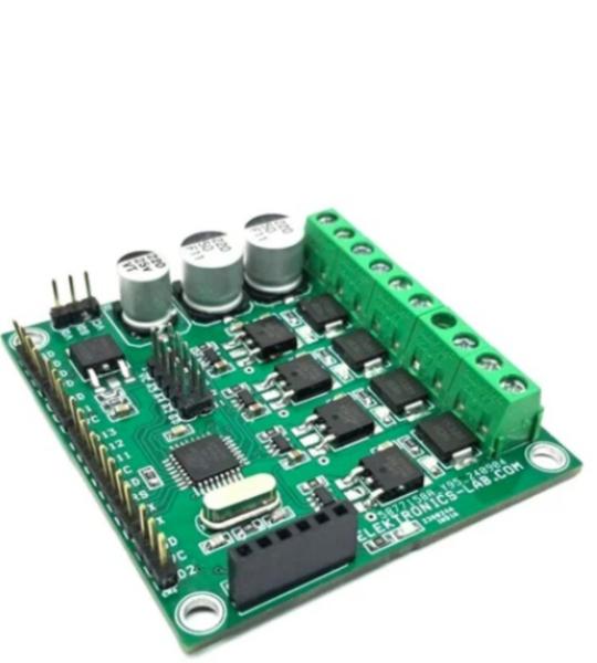
This Bluetooth Smart LED Dimmer, 4 Channel ON/OFF Switch is a versatile device that enables users to control various devices, including lights, fans, and DC motors, using a Bluetooth app on an Android device. The device features a 4-channel dimmer that can handle inductive or resistive loads with a power supply range of 12V to 48V and a current capacity of up to 3A per channel. The project is designed to work with DC loads and includes freewheeling diodes across all 4 MOSFETs to handle inductive loads such as DC motors and solenoids. The device requires a dual power supply, with a logic supply of 12V-15V and a load supply of 12V to 48V. However, it can also operate with a single supply of 12V-15V by tying the VDD and VL pins together.
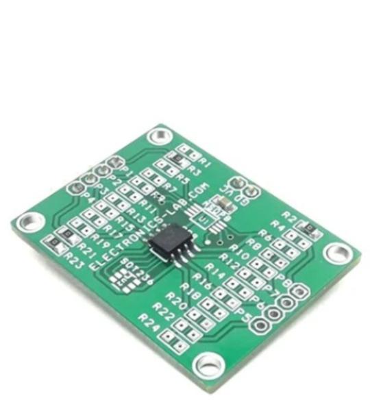
This is an 8-pin SOIC/MSOP/SOT23-3/4/5/6 prototype board. This is a blank PCB that allows the operation of many chips from various manufacturers. Each device pin is connected to a pull-up resistor, a pull-down resistor, an in-line resistor, and a capacitor on VCC. All pins are provided with a male header connector.
Cookie preferences