USD
 INR

Call Us Now
+91 9106756572
The project published here is a solid-state power switch with current limiting that prevents damage to host devices from faulty load conditions. This analog current limit switch has low on-resistance P-channel MOSFET and INA202 driver IC from Texas Instrument. The project operates from input voltage in the range of 5V to 24V and can handle currents up to 2A. The versatile project can be used in Smart Power applications. It is widely used to clamp the overload current and deliver a constant current.
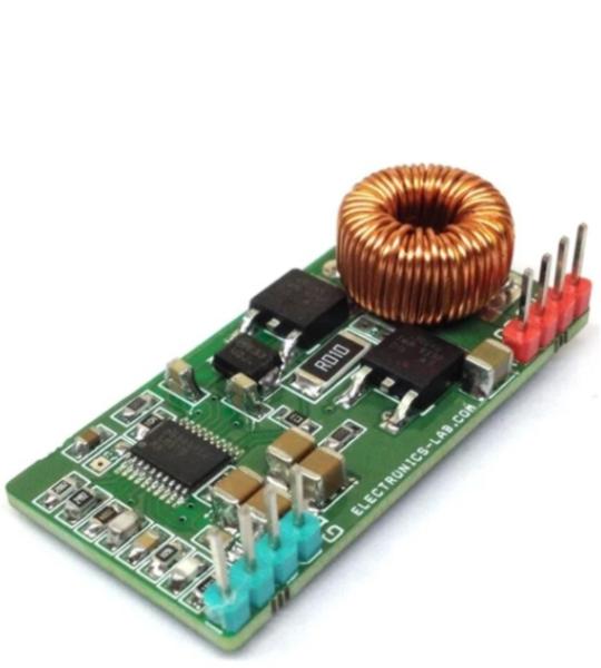
This module is a non-isolated 7A DC-DC converter. The module can convert any DC voltage between 7V to 50V to a 5V DC with load current up to 7A. The project has been designed around LM5116 Wide Range Synchronous Buck Controller IC. The design includes 6uH toroid inductor and two N channel MOSFETS. The operating frequency is 250 KHz.
The LM5116 is a synchronous buck controller intended for step-down regulator applications from a high-voltage or widely varying input supply. The control method is based upon current mode control utilizing an emulated current ramp. Current mode control provides inherent line feed-forward, cycle-by-cycle current limiting, and ease-of-loop compensation. The use of an emulated control ramp reduces noise sensitivity of the pulse-width modulation circuit, allowing reliable control of very small duty cycles necessary in high-input voltage applications.
The operating frequency is programmable from 50 kHz to 1 MHz and the LM5116 drives external high-side and low-side NMOS power switches with adaptive dead-time control. A user-selectable diode emulation mode enables discontinuous operation mode, for improved efficiency at light load conditions. A low quiescent current shutdown disables the controller and consumes less than 10 µA of total input current.
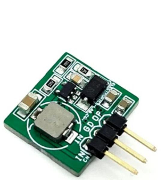
This compact boost converter module that steps up a 5V DC input to a 12V DC output, utilizing the LM2733 switching regulator. The design emphasizes high power density through the use of the small SOT-23 package, minimal inductor and capacitor sizes, and high switching frequencies 1.6 MHz. Protection is provided through cycle-by-cycle current limiting and thermal shutdown. Internal compensation simplifies design and reduces component count.
This compact module shown here is a Continuous Conduction Mode (CCM) Power Factor Correction Step up Pre-Converter. All-important inputs and output pins are broken out for use in your application, making this board hackable! Please refer to the datasheet of the NCP1654 chip for easy alteration and configuration of the board as per requirements. This board controls the power switch conduction time (PWM) in fixed frequency mode and is dependent on the instantaneous coil current. This module drastically simplifies the PFC implementation scheme. It also integrates high safety features that make the NCP1654 module ideal for robust and compact PFC stages like an effective input power runaway clamping circuit. Please refer to the application schematic to create a powerful PFC using this pre-driver module. The chip is available with various options for frequency such as 65Khz, 133Khz, and 200Khz. Choose the appropriate chip as per frequency requirement This project is tested with a 65Khz oscillator chip.
This is an automotive-grade self-oscillation 50% duty cycle half-bridge module built using the AUIR2085S chip from Infineon. The project consists of 2 x N-channel MOSFETs, and the module provides a primary side control solution to enable Half-Bridge DC-bus converters. The module is a self-oscillating half-bridge driver with 50% duty cycle ideally suited for 10V – 15V half-bridge DC-bus converters. The board is also suitable for push-pull converters. Each channel frequency is equal to fOSC, which can be set by selecting RT (R2+PR1) & CT-(C7), Dead-time can be controlled through proper selection of CT range from 50ns to 200ns. Internal soft-start increases the pulse width during power-up and maintains pulse width matching for the high and low outputs throughout the start-up cycle. Typically, the soft-start duty cycle varies beginning from 5-10% ramping up to about 50% over 1000 cycles. The AUIR2085S initiates a soft start at power up and after every overcurrent condition. Undervoltage lockout prevents operation if VCC is less than 7.5V.
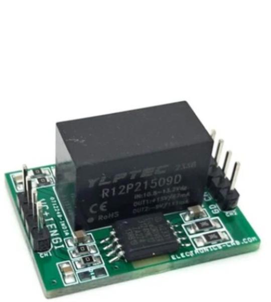
This project design consists of galvanically isolated single channel gate driver IC and dedicated isolated DC-DC gate drive power supply with bipolar output +15V/-9V. This compact module can control IGBTs in inverters. The isolated high current IGBT gate driver module is a simple solution for power drivers, consisting of a gate driver chip 1ED3124MC12H and an isolated 2W DC-DC converter (R12P21509D). This module is optimized for high-frequency operations and can provide high gate driver currents up to 14A, making it suitable for applications such as half-bridge, full-bridge, and single IGBT.
Logic input: for the output switching behavior there are two possible input modes to control the IGBT. At non-inverting mode IN+ controls the driver output while IN- is set to low. At inverting mode IN- controls the driver output while IN+ is set to high. A minimum input pulse width is defined to filter occasional glitches.
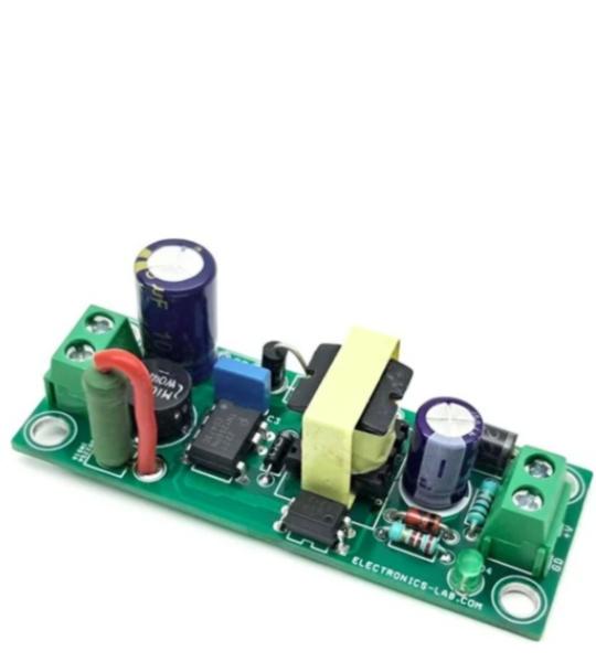
This compact Switch-Mode Power Supply (SMPS) is built around the TNY266 chip, offering a cost-effective solution for various applications, including power adapters and LED drivers. The SMPS consists of a bridge rectifier, a DC bus capacitor, the TNY266 switch IC, a rectifier diode, and a PC817 optocoupler for feedback and fault condition monitoring.
The board features screw terminals for easy connection of AC input and DC output, as well as an onboard LED indicator for output voltage. Notably, no auxiliary power is required to drive the chip, making it a highly efficient design.
The project presented here is a PWM current driver for solenoids, Relays, and valves. The board will regulate the current with a well-controlled waveform to activate and reduce power dissipation at the same time. The solenoid current is ramped up fast to ensure the opening of the valve or relay. After the initial ramping, the solenoid current is kept at peak value to ensure the correct operation, after which it is reduced to a lower hold level in order to avoid thermal problems and reduce power dissipation.
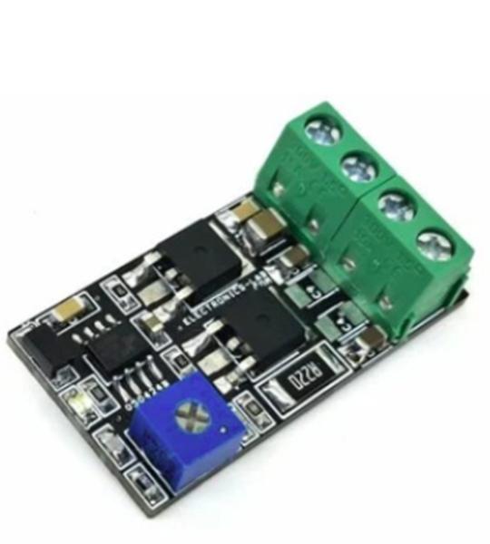
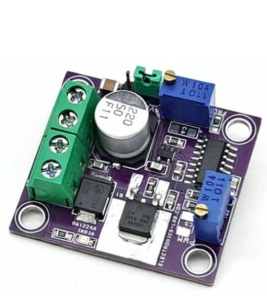
The project presented here is a high-current adjustable PWM (Pulse Width Modulation) source, designed to drive various loads such as PTC (Positive Temperature Coefficient) devices, DC motors, solenoids, high-power LEDs, and valves. The project consists of three main components: an SG3525 PWM generator, an MCP4015 MOSFET gate driver, and a MOSFET for load driving.
The key features of this project include adjustable PWM and frequency settings. A multiturn trimmer pot is provided for precise frequency and PWM adjustment, allowing for fine-tuning of the output signal. Screw terminals are included for easy connection of the load and power supply, and an onboard LED indicator provides visual confirmation of power presence.
The board can handle currents up to 3A, with a PWM duty cycle adjustment range of 0 to 100%. The frequency span is also adjustable, ranging from 500 Hz to 6.5 kHz. This makes the project suitable for a wide range of applications that require high-current PWM control.
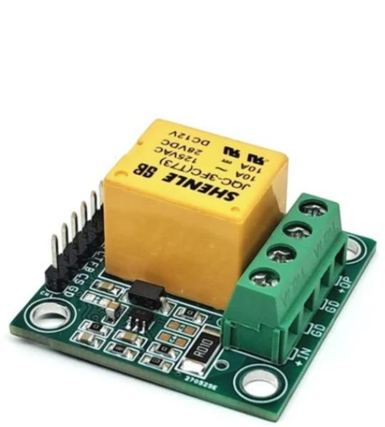
This simple project allows users to design an under-voltage, over-voltage, under-current, and over-current protection switch. It is a highly useful system for safeguarding electrical loads against abnormal power or current conditions.
The project features a relay with optocoupler input, a current-sensing circuit based on the INA195 amplifier, a 10mΩ shunt resistor, and a voltage divider network for voltage feedback. It is primarily designed for low-voltage and low-current applications up to 4A, but the relay can handle loads up to 5 A at supply voltages up to 48 V.
The system can be easily controlled using an Arduino or other microcontroller. Voltage and current feedback signals are fed into the microcontroller’s ADC pins for measurement, while the relay can be switched using a 5 V control signal from the processor.
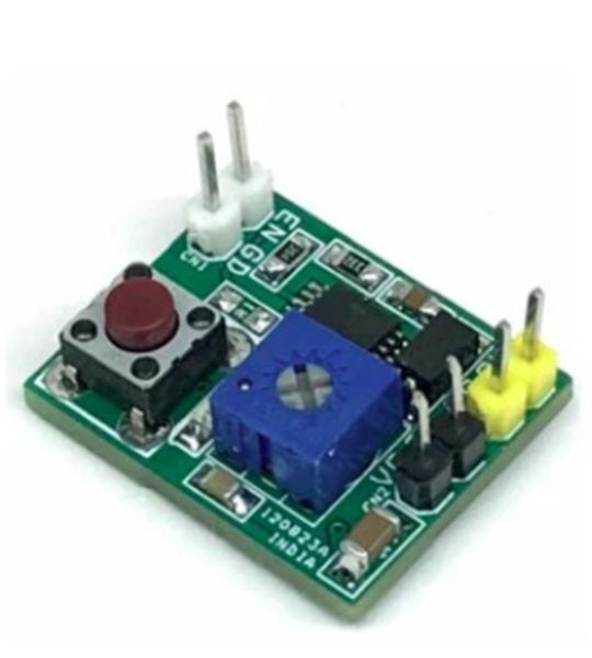
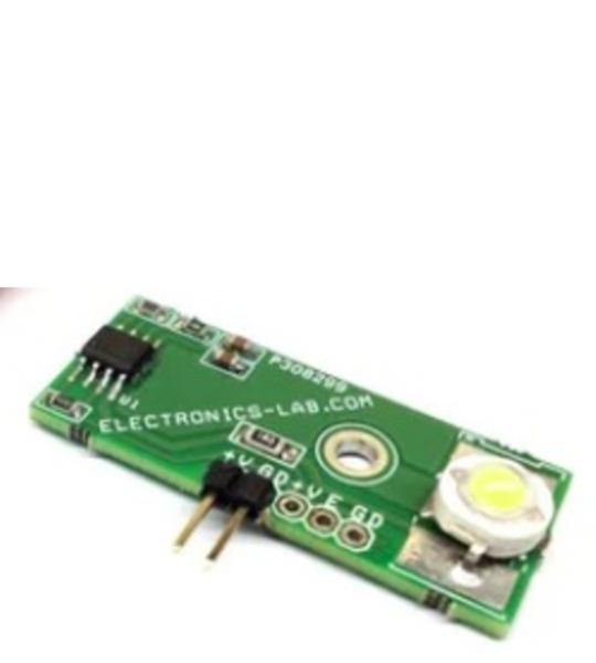
Contact-less controlled automatic wardrobe light turns on the LED when you open the wardrobe door. Τhe project is based on Hall effect IC including LED driver and tiny magnet. Board doesn’t require any mechanical switch. When magnet is close to the board, LED is off, when you open the wardrobe door magnet goes far from hall IC and its turn on the LED, the IC also has special features like soft start and soft off. This board can be used in other applications like Automotive Gloves boxes and Storage, task lighting, automotive vanity mirrors. The APS13568 is the heart of the project. The IC can drive LED current up to 150mA. I have set the current 100mA approx. with help of R3. C2 is provided to set the FADE-IN/FADE-OUT time. The value of C2 can be changed as per application requirement.
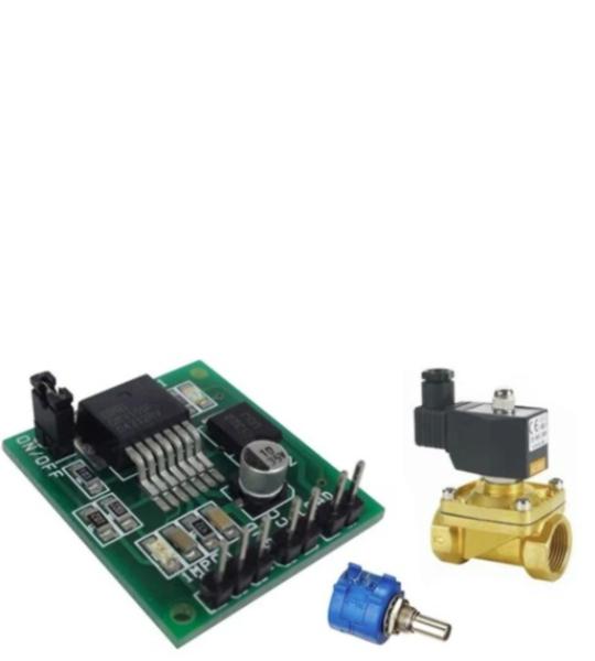
The DRV101 is a low-side power switch employing a pulse-width modulated (PWM) output. Its rugged design is optimized for driving electromechanical devices such as valves, solenoids, relays, actuators, and positioners. The DRV101 module is also ideal for driving thermal devices such as heaters and lamps. PWM operation conserves power and reduces heat rise, resulting in higher reliability. In addition, an adjustable PWM potentiometer allows fine control of the power delivered to the load. Time from dc output to PWM output is externally adjustable. The DRV101 can be set to provide a strong initial closure, automatically switching to a soft hold mode for power savings. The duty cycle can be controlled by a potentiometer, analog voltage, or digital-to-analog converter for versatility. A flag output LED D2 indicates thermal shutdown and over/under current limit. A wide supply range allows use with a variety of actuators.
Cookie preferences