USD
 INR

Call Us Now
+91 9106756572
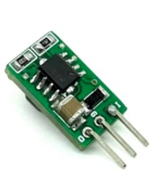
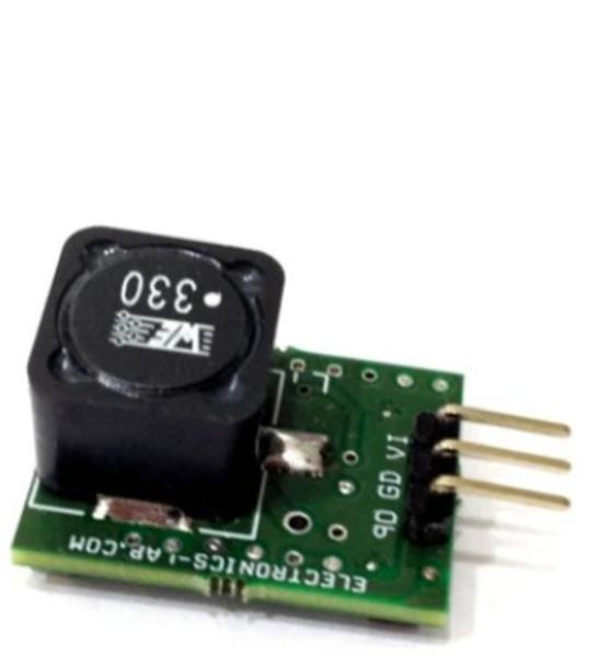
The project demonstrated here is a small-size solution, high-efficiency, low-cost, and low-EMI step-up DC/DC module for LDO regulator replacement. This small size module helps save on solution size and cost while also eliminating the need for a heatsink. The module takes up the same amount of space as a TO-220 package and is pin-to-pin compatible with TO-220 regulators, such as LM7805. The project is based on LM3578, which is a switching regulator that can easily be set up for such DC-to-DC voltage conversion circuits as the buck, boost, and inverting configurations. In this board, the chip is configured as a boost converter. Switching frequency sets at 100Khz. The project provides 24V output from 12V input. The project can output up to 20mA of current but it is safe to draw continuous 10mA.
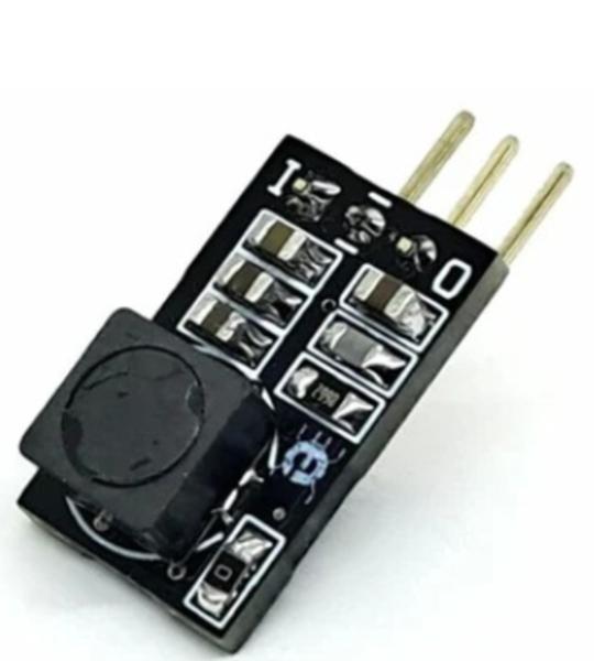
We are introducing a compact DC-DC converter that delivers a 5V output with a load current of up to 1.5A, powered by an input supply of 24V to 26V DC. This innovative project boasts key features such as soft start, thermal shutdown, and overcurrent protection. Built using the MP2345 TSOT23-6 DC-DC Converter, this mini board offers a significant advantage over traditional LDOs like LM7805, occupying a much smaller area while providing more power and generating minimal heat.
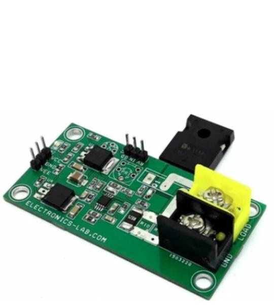
This is a very precise Electronic Load project built using the ultra-Precision, Low-Noise OPAMP MAX44251 from Analog Devices. The project can sink current from a power source. It can be used as test gear for power supplies, chargers, solar panels, batteries, and DC-DC converters. The resistor R11 acts as a shunt, OPAMPs convert current into voltage, 2nd op-amp, and Q1 MOSFET are used to control the load current. A Multi-turn potentiometer helps to adjust the load current in the range of 0 to 1A. The supply voltage is up to 60V DC. The board works with dual supply +/-15V DC and draws a few milli amps. LM317 regulator provides 12V DC top op-amp and LM337 provides regulated -7V supply to op-amp. At full load, MOSFET Q1 produces lots of heat, and a fan and large heatsink on MOSFET will help cool it down. Users may use a current meter in series to load to display the current. Optional onboard Trimmer potentiometer provided in case external potentiometer is not required.
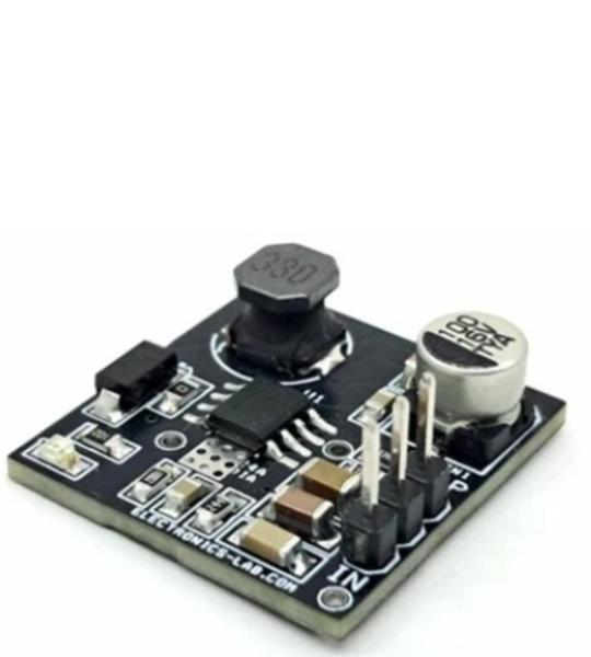
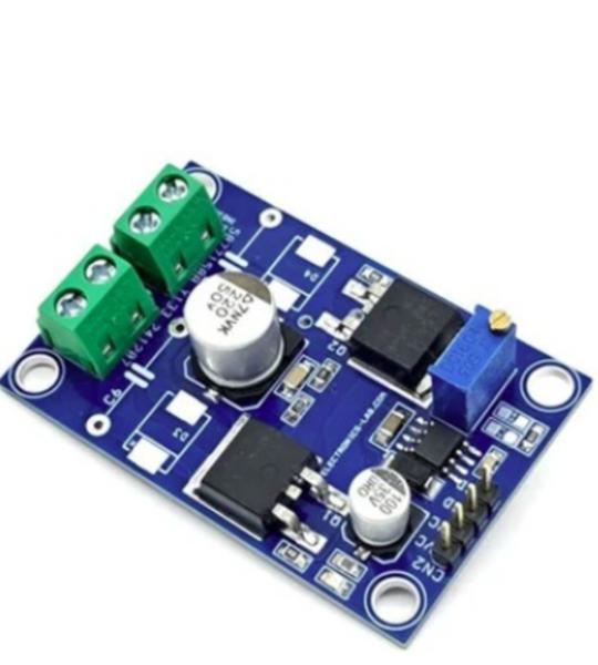
This high-voltage buck converter is specifically designed for e-scooter and e-bike control power supply applications, but its versatility also makes it suitable for use in solar energy systems, automotive systems, and industrial power supplies. This converter utilizes the MPS9486 chip, a 4.5V-to-95V-input, 1A-output step-down converter that provides efficient power conversion.
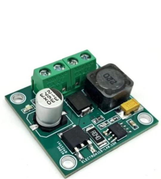
This is a 24-48V input voltage range 3A output current DC-DC Converter using BD9G341AEFJ IC from ROHM semiconductor. This IC is ideal for high-voltage to low-voltage converter with 3A output current. The pin configuration of the board with 3 Pin horizontal mounting of the regulator is similar to the LM7805 LDO regulator and is suitable to use this IC as a replacement which provides more current and takes high voltage input.
This is a Half Bridge with Inbuilt Oscillator project that uses the NCP1392B, a self-oscillating high-voltage MOSFET driver, and two IRF540 MOSFETs. This project is specifically designed for applications that employ half-bridge topology.
The operating frequency of the driver can be adjusted from 25 kHz to 100 kHz using a trimmer potentiometer (PR1). Additionally, the project features adjustable brown-out protection, ensuring that the bulk voltage operates within the correct range. An internal 100 ms or 12.6 ms PFC delay timer guarantees that the main downstream converter will be turned on only when the bulk voltage is fully stabilized. The device also provides a fixed dead time, which helps reduce shoot-through current.
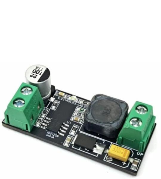
This compact step-up DC-DC converter delivers up to 90% efficiency with load currents up to 1A. The design is based on the MAX1771, which uses a unique current-limited Pulse Frequency Modulation (PFM) control scheme. This architecture combines the high efficiency of traditional PWM converters at heavy loads while consuming less than 110µA supply current, significantly lower than the 2mA to 10mA typically required by PWM-based designs.
A buck converter board has been developed utilizing the BD9G341AEFJ, a non-synchronous DC/DC converter. This board accepts a wide input voltage range of 12V to 76V DC and generates a regulated 5V DC output. The BD9G341AEFJ features an integrated 150mΩ N-channel MOSFET and a programmable switching frequency, adjustable from 50kHz to 750kHz. On this board, the switching frequency is fixed at 200kHz using resistor R5. To ensure reliable operation, the board incorporates several protection features. A fixed soft-start circuit minimizes inrush current during startup. Additionally, the board includes Under-Voltage Lockout (UVLO), Thermal Shutdown Detection (TSD), Over-Current Protection (OCP), and Over-Voltage Protection (OVP) circuits. The UVLO threshold and hysteresis are configured externally using resistors R1 and R4 connected to the EN (Enable) pin.
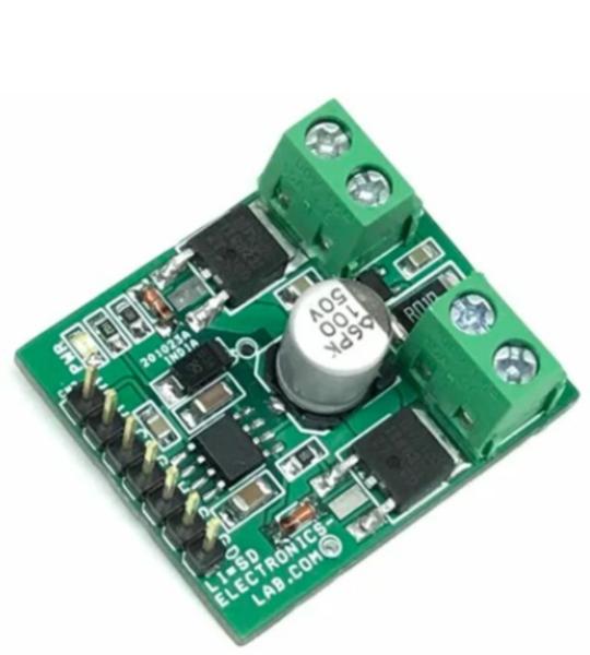
A Half-bridge converter is widely used in applications such as DC-DC converters, switch mode power supplies, inverters, motor drivers, resistive loads, and solenoid drivers. This project consists of an IR2104 Half-bridge driver chip, 2 x DPAK MOSFETS, and an INA293 precision current sense amplifier. The IR2104 is a half-bridge, high voltage, high-speed power MOSFET and IGBT driver with dependent high and low side referenced output channels. It drives high and low-side N-channel MOSFETs, INA293 chip measures the load current across the shunt resistor connected to the output.
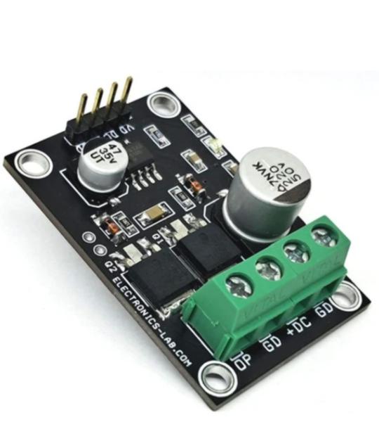
This is a Half-bridge module based on the LM5104 chip, which is a high-voltage gate driver. This High-Voltage Gate Driver is designed to drive both the high-side and the low-side N-channel MOSFETs in a synchronous buck configuration. The floating high-side driver can work with supply voltages up to 100V. The high-side and low-side gate drivers are controlled from a single PWM input. Each state change is controlled adaptively to prevent shoot-through issues. In addition to the adaptive transition timing, an additional delay time can be added, proportional to an external setting resistor. An integrated high-voltage diode is provided to charge the high-side gate drive bootstrap capacitor. A robust level shifter operates at high speed while consuming low power and providing clean level transitions from the control logic to the high-side gate driver. Undervoltage lockout is provided on both the low-side and the high-side power rails.
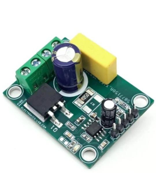
This IGBT driver module is a low-side gate driver that features integrated over-current protection. The primary functions of this module are its built-in over-current protection and enable/fault output capabilities. The board’s main components include the gate driver chip (1ED44176N01F), an SMD D2PK IGBT, and a current sense resistor. The chip is equipped with an over-current protection function, which has a typical threshold of 0.5V at the OCP (Over-Current Protection) point. When an over-current condition occurs, the driver output is automatically switched off. Simultaneously, the EN/FLT (Enable/Fault) pin is internally pulled down, and an internal current source charges the capacitor (C4) connected between the FLTC and VSS pins to program the fault clear time. This module is capable of driving loads up to 1A and can drive higher current with forced air cooling. It can operate within a load power supply range of 80-400V DC, making it a reliable and efficient solution for various applications.
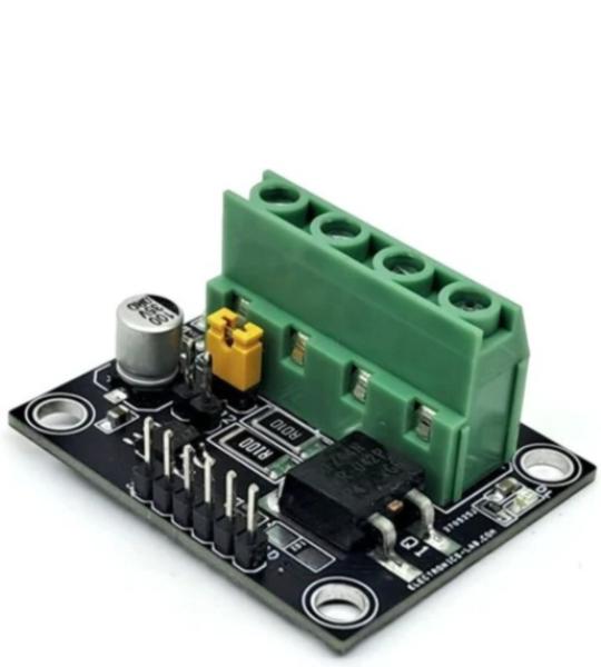
This product is designed to protect the load from over-current conditions using the LT1910 fault-protected high-side switch controller. When the internal drain comparator detects that the switch current exceeds the preset threshold, the LT1910 immediately turns off the switch and asserts a fault flag.
Cookie preferences